
Network Router User Manual


GFK-1535A Appendix A Operation of the Genius Bus A-7
A
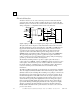
Genius Transceiver Electrical Specification
Property Min Max
Normal peak voltage Vp into 78 ohm terminated cable (1) 3.5 volts 5.5 volts
Normal peak voltage Vp into 150 ohm terminated cable (1) 6.0 volts 9.5 volts
Rated bus impedance (2) 78 ohms
Maximum output voltage (SER 1 and 2 open) (3) : Peak: 35 volts
RMS: 15 volts
Maximum output current (SER 1 and 2 shorted together) : Peak: 180 milliamp
RMS: 50 milliamp
Transmitter source resistance 80 ohms 140 ohms
Transmitter source inductance (transformer leakage inductance) 10 microhenries
Receiver input threshold; +Vr, -Vr (4) 0.7 volt 1.1 volt
Receive mode input impedance 10 K ohm
Receive mode load inductance (transformer shunt inductance) 6 millihenries 12 millihenries
Receiver common mode rejection (DC to 1 MHZ) 60 dB
Shield capacitor termination 0.1 microfarad
Isolation, serial bus to circuit, continuous 240 volts AC
(1) Vp may vary among various module types.
(2) Rated load is half cable impedance when termination is included.
(3) Peak open circuit voltage contains underdamped ringing due to lack of
termination.
(4) Input voltages between +Vr and -Vr thresholds are ignored.
Bus Errors
Most capacitively- and magnetically-coupled noise shows up as common mode
voltage on the bus. The bus provides a 60 dB common mode rejection ratio. A noise
spike above 1000 volts would be required to corrupt the data. The bus receivers
filter out corrupted data and perform a 6-bit cyclic redundancy check to reject bad
data. Corrupted signals due to noise show up as missed data rather than incorrect
data. The bus continues operating to the maximum extent possible when bus errors
are detected; random bus errors do not shut down communications. Bad data is
rejected by the receiving device and excessive errors are reported to the controller.