T1 MODE T1 S F D M KL FA DIS MPH KTS Pilot I ™ Owner’s Manual Pilot I Displays, Speedometer in MPH and Knots Trip Log Clock Voltmeter Air & Surface Temp.
Description Key Pad Functions Installation 4 pin Connector 6 pin Connector Operations General Modes Power On Illumination Normal Mode Select Mode Activating Selecting upper or lower display Selecting display function Edit Mode Upper Display Functions Depth Sounder Setting Shallow Alarm Setting Deep Alarm Setting Keel Offset Loss of signal Timer Selecting Timer functions Starting/Stopping Timer Resetting Timer Clock Selection Clock functions Setting the Clock Page 1 Page 2 Page 2 Page 3 Page 3 Page 3 Page 3
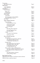
Key Pad Functions Display Timer (Hrs. & Min.) Timer (Min. & Sec.) Clock Function Indicator T1 Depth Sounder Shallow Alarm Deep Alarm Keel Offset MODE T1 S F D M KL FA DIS Voltmeter Air Temp. Water Temp.
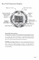
Used for all splices. Wires 6-Pin Male Connector 6-Pin Female Connector Heat Shrink Tube (red or blue) Metal Butt Connector (red or blue). Used for all splices. Note: For wiring diagram for the 6 - Pin connector see Yamaha (HN0362) Others (HN0365) 4-Pin Female Connector 4-Pin Male Connector Note: For wiring diagram for the 4 - Pin connector see Yamaha (HN0362) Others (HN0365) Installation: CAUTION: Disconnect the battery during installation.
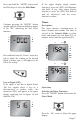
Operation: Power ON: The Pilot I instrument will turn on when the ignition key switch is set to the run position. When the ignition key switch is turned to the off position, the Pilot I will turn off. *If the mode button is accidentally pressed for an extended period of time the unit will enter a diagnostic OFF Mode. This can be remedied by pressing the “Mode” button again to turn the unit on. Normal Mode: Pilot is operating showing the last selected Functions.
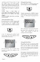
Selecting upper or lower active display: Activate the Select Mode and while the display is flashing, press the “Up” arrow selected active display and the Pilot will beep each time the “MODE” button is pressed. T1 T1 to select the upper display as active S F D M KL FA DIS MPH KTS Stop at the desired function. or the “Down” arrow to select the lower display as the active display.
If no buttons are pushed within 5 seconds, the Pilot will revert automatically to the Normal Mode. You can also enter the Edit Mode while in the Select Mode. The Pilot display will then stop flashing (Select Mode) indicating the change to the Edit Mode. (The operation of various edit modes will be separately explained for each function throughout the manual. Continue pressing the “MODE” button again until the Function Indicator is pointing to FT, M or FA.
will flash on the LCD next to the “S” and the audible alarm will sound rapidly. When the deep depth setting is read by the depth sounder, the Function Indicator will flash on the LCD next to the “D” and the audible alarm will sound at 2 beeps per second. NOTE: Once a keel offset is programmed, the depth below the keel will activate the shallow and deep alarms. NOTE: To fully deactivate an alarm, reset it to zero.
Press and hold the “MODE” button until the Pilot beeps to select the Edit Mode. If the upper display depth sounder function is active the (SIG) will illuminate and hold. If any other upper display function is active the (SIG) will flash on and off alternately with the active function’s readout. Timer: Continue pressing the “MODE” button quickly until the Function Indicator points to the “KL” indicating the keel offset function.
Clock: Description: The clock will run continuously as long as power is applied to the Pilot. The clock reads hours and minutes. Continue pressing the “MODE” button Operation: Selecting the Clock Function. Press the “MODE” button and activate the Select Mode. again until the Function Indicator is pointing to either the left(T1) or the right(T1). T1 T1 S F D M KL Press the “Up” arrow to select the upper display. FA DIS MPH KTS Starting and Stopping the Timer.
Setting the clock: Press and hold the “MODE” button until the Pilot beeps to select the Edit Mode. Press the “Up” or “Down” arrow keypads once to set each minute. Minutes: Quick Press Press and hold the “Up” or “Down” arrow keypads to set the hours. (The minutes will continuously advance in 10-minute intervals to change the hours.) Hours: reading to match a GPS or charted distance run. Calibrating the distance Log also automatically calibrates the Speedometer.
Selecting the Speedometer Units. Press and hold the “MODE” button until the Pilot beeps to select the Edit Mode. quickly until the lower display reads “C” T1 Continue pressing the “MODE” button quickly until the lower display reads “Un” (units). T1 T1 S F D M KL FA DIS MPH T1 KTS S F D M KL FA DIS MPH (calibration). Press either the “Up” or “Down” arrow button to change the speed reading to the desired speed.
Continue pressing the “MODE” button again until the Function Indicator is T1 Calibrating the Distance Log: Press and hold the “MODE”button until the Pilot beeps to select the Edit Mode. T1 S F D M FA KL DIS MPH KTS pointing to DIS. (The Function Indicator will also automatically point to the last unit type selected. You are now in the Distance Log Function Continue pressing the “MODE” button quickly until the lower display reads “c” (calibration).
Press either the “Up” or “Down” arrow button to clear the Log reading to zero. T1 T1 S F D M KL FA DIS MPH KTS Water & Air Temperature / Bait-well Description: The Pilot I will monitor water surface temperature. The (Setting units Fahrenheit (F), or Centigrade (C), in either function sets the units for both). (A second temperature, either air or bait-well may be monitored when the unit is equipped with the optional sender.
T1 T1 S F D M KL FA Continue pressing the “MODE” button again until the display shows 00.0 and no other Lower Display Function Indicator is active except the one pointing to the Battery icon. DIS T1 MPH T1 KTS Voltmeter: S F D M FA KL DIS Description: The Voltmeter continuously monitors the battery system voltage supplied to the Pilot I. The Voltmeter has a user adjustable low and high voltage alarm feature.
Press the “MODE” button. T1 T1 S F D M KL FA DIS The upper display changes to “bAtH” and the lower display shows the current high voltage warning setting. T1 S F M FA DIS MPH KTS Press either the “Up” or “Down” arrow button to adjust the high voltage alarm setting. Bar Graph Function Display Description: The bar graph provides a continuous display of the battery system voltage supplied to Pilot I. Each element of the bar graph represents one (1) volt. Voltages from 10.5 vDC to 17.
This page left blank intentionally.
Harness HN0362 4 - pin connector Yamaha adaptor To Pilot I 4- pin connector(CN0082) Pin A Pin B Pin C Pin D Red Purple Black Blue +12 Battery +12 Ignition Ground Depth Sounder signal ECR 2065 2/12/02 Paddle Wheel triducer Shrink Tubing or Wrap Blue Blue Green (Depth Sounder Signal) Black Black (Depth Sounder ( - )) White Red (+12 vDC) Red Purple Brown Black Shield (Ground) Yellow Black (+12 vDC) (Ignition) Red (Grnd) Multi-bullets to Yamaha Engine Harness
Harness HN0362 6 - pin connector Yamaha adaptor To Pilot I 2x PJ0005 Shrink Tubing or Wrap White/Blue Green Stripe (Paddle Wheel Signal) White Air Temp.Sensor White White Red Water Temp.
Harness HN0365 4 - pin connector To Pilot I 4- pin connector(CN0082) Pin A Pin B Pin C Pin D Red Purple Black Blue +12 Battery +12 Ignition Depth Sounder (-) Depth Sounder signal ECR 2152 03/07/02 Paddle Wheel triducer Shrink Tubing or Wrap Blue Blue Green (Depth Sounder Signal) Black Black Black Purple Red (Depth Sounder ( - )) Red (+12 vDC) Brown Shield (Ground) (+12 vDC) (Ignition) (Grnd) White
Harness HN0365 6 - pin connector To Pilot I 2x PJ0005 Shrink Tubing or Wrap White/Blue Green Stripe (Paddle Wheel Signal) White Tan/White Stripe Tan/Blue Stripe White Air Temp.Sensor Water Temp.
NOTES
Copyright 2003 by the Thomas G. Faria Corporation, Uncasville CT No part of this publication may by reproduced in any form, in an electronic retrieval system or otherwise, without the prior written permission of the company.