Owner’s Manual GM ALDL MG2000™ Tachometer IS0195 rev.
IS0195 x7 w/ corrections Mark ups 12/20/05
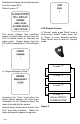
Index Figure 1 Default screens Description Normal Mode Contrast and Lighting Displayed Functions Default screen 1 Default screen 2 Default screen 3 Default screen 4 Figure 2 Screen Sequence Figure 3 LCD Display Screens Edit Mode Functions that are adjusted in Edit Mode.
This page left blank intentionally.
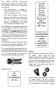
The FARIA MG2000 Tachometer combines the features of an ECU serial bus gateway and several instruments into one unit: • The tachometer is analog in appearance but driven by a stepper motor for digital accuracy. • The high resolution LCD screen displays information for many other functions and the various “screens” can be configured as the user wishes. As received, the screens are configured as shown in Fig. 1.
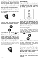
(see Figure 2). Press the “Mode” button to exit the “screen selection mode” and return to “Normal” mode or do not push any buttons for 4 seconds and the current screen will stay selected and the unit will return to “Normal” mode (see Figure 3). In the “Normal” operation mode, press the “Mode” and “Up” buttons to change to the “Edit” menus (see Figure 3 and “Edit” mode below). Press the “Down” or “Up” buttons to cycle between the available “Edit” functions.
OIL PRESSURE Analog input. Displays information from the analog oil pressure sender. Default Screen “2” To adjust the lighting intensity of all of the instruments in the system, press and hold both the “Down” and “Up” buttons for 2 seconds. The lighting intensity may now be adjusted by using the “Down” or “Up” buttons. Fuel Left Return to the “Normal” mode by pressing and holding both the “Down” and “Up” buttons for 2 seconds.
Displays the Engine Hours data received from the engine ECU. Default screen “4” LCD Display Screens: This screen displays fault conditions based on engine data received from the ECU or alarms based on internally set alarm points. Engine alarms from the ECU will be displayed as “Check Engine !” In “Normal” mode, press “Mode” once to enter screen “Select” mode, press “Up” or “Down” to move between screens. Press “Mode” once to return to “Normal” mode. Screen “1” or “Engine Emergency Stop !”.
40 1. 2. 3. 4. 5. 6. 7. 8. 9. 10. 11. 12. 13. 14.
This page left blank intentionally.
Edit Mode The “Edit” mode is used to adjust or set the values of numerous functions and options in the MG2000. The procedure below specifies the steps to be taken in the “Edit” mode to adjust / set each option. To enter “Edit” mode, press the “Mode” and “Up” buttons while in “Normal” mode Functions that are set or adjusted in the “Edit” mode: 1. Select Default Screen 2. Reset Fuel Used 3. Set Fuel Tank Full 4. Set Amount of Fuel 5. Organize User Screens 6. Select Gauge Range 7. Select Fuel Sender 8.
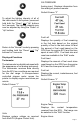
1 Display 2 Next 3 Screen 1 Reset 2 Fuel 3 Used 1 Set 2 Fuel Tank 3 Full Press and hold the “Up” and “Down” buttons for 2 seconds to select this screen as the “default screen” and exit. Press “Up” or “Down” to select another screen. Repeat until desired “Default Screen” is selected. Press “Up” or “Down” to select another function or “Mode” to return to “Normal” mode. Reset “Fuel Used” Press and hold the “Up” and “Down” buttons for 2 seconds to reset “Fuel Used” to zero (0).
Set “Amount of Fuel” 1 Set 2 Amount 3 Of Fuel NOTE: If a known amount of fuel is in the fuel tank but it is not full, this function can be used to indicate the amount of fuel available. The “Fuel Left” function will then use the amount of fuel entered to calculate the “Fuel Left.” Press and hold the “Up” and “Down” buttons for 2 seconds to select “Current Amount of Fuel.” Press “Up” or “Down” to set the amount of fuel known to be in the fuel tank.
Press and hold the “Up” and “Down” buttons for 2 seconds to save selection for Screen 1, line 1 and advance to Screen 1, line 2. Press “Mode” to exit with no change made. Refer to the list of available functions in the ownerʼs manual. Press and hold “Up” or “Down” to select the number of the function to be displayed in screen 1, line 2.
Press and hold the “Up” and “Down” buttons for 2 seconds to select “Oil Pressure Dial.” Press “Up” or “Down” to select another “Gauge Range.” Press “Mode” to return to the “Edit” mode. Press “Up” or “Down” to scroll through the selections.
Select “Water Press Dial” 1 Select 2 Water Press 3 Dial Press and hold the “Up” and “Down” buttons for 2 seconds to select “Water Press Dial.” Press “Up” or “Down” to select another “Gauge Range.” Press “Mode” to return to the “Edit” mode. Press “Up” or “Down” to scroll through the selections. When the correct choice is next to the selection arrow, Press and hold the “Up” and “Down” buttons for 2 seconds to save the selection and return to “Gauge Range” selection.
1 > USA Press “Up” or “Down” to scroll through the selections. 2 240 – 33 ohm When the correct choice is next to the selection arrow, Press and hold the “Up” and “Down” buttons for 2 seconds to save the selection and return to the “Edit” mode. 3 EU 4 10 – 180 ohm 5 Centroid 6 Press “Up” or “Down” to select another function or “Mode” to return to the “Normal” mode.
Press “Up” or “Down” to scroll through the selections. 1 When the correct choice is next to the selection arrow, Press and hold the “Up” and “Down” buttons for 2 seconds to save the selection and return to select “Units.” 2 Select “Volume Units” > PSI BAR 3 1 Select 2 Volume 3 Units Press and hold the “Up” and “Down” buttons for 2 seconds to select “volume units” Press “Up” or “Down” to select another choice of “Units” Press “Up” or “Down” to scroll through the selections.
Press “Up” or “Down” to scroll through the selections. 1 When the correct choice is next to the selection arrow, Press and hold the “Up” and “Down” buttons for 2 seconds to save the selection and return to select “Units.” 2 kM 3 NM 1 Select 2 Depth 3 Units Select “Depth Units” > Miles Press and hold the “Up” and “Down” buttons for 2 seconds to select “Depth Units” Press “Up” or “Down” to select another choice of “Units.” Press “Up” or “Down” to scroll through the selections.
If there is no tank size available in the list that matches your tank size, scroll to the next screen. Press “Up” or “Down” to set the fuel tank size displayed on the screen to match your fuel tank size. Line 4 value will adjust. When set, Press and hold the “Up” and “Down” buttons for 2 seconds to save and exit.
Press and hold the “Up” and “Down” buttons for 2 seconds to save “Full Tank” calibration and exit. Press “Up” or “Down” to select another function or “Mode” to return to “Normal” mode. Select “Low Fuel Alarm” setting 1 Low 2 Fuel 3 Alarm 1 Low 2 Fuel 3 XX.X 1 Software Id 2 and 3 Revision 4 Minigateway 5 - Rev - 1 Select 2 Self 3 Test Press and hold the “Up” and “Down” buttons for 2 seconds to select “Low Fuel Alarm.” Press “Up” or “Down” to select another function.
1 The This screen will display for 10 seconds. 2 Self The horn will sound three times. 3 Test The warning lights will flash three times. 4 Mode The backlights will flash three times. 5 Is in 6 Operation When “Self Test” is complete the unit will return to the “Edit” mode. Press “Up” or “Down” to select another function or “Mode” to return to “Normal” mode.
Alarm Mode The “Alarm” screen appears only if an alarm condition exists. The alarm condition may be a warning sent from the engine ECU or a “Local” alarm such as “Low Fuel”. When an alarm condition occurs, the “Alarm Screen” will appear and the screens described below will be displayed. alarm will re-occur after a period of time to ensure that the user remembers the alarm condition. Once an alarm condition has been corrected, the alarm screen, horn, and warning lights will no longer be displayed.
Press and hold “Up” and “Down” for 2 seconds to view alarm messages. Press “Mode” to silence alarm horn and return to “Run” mode. LED will continue to function as stated until engine alarm(s) is no longer sent by ECU.
1 2 3 1 2 3 1 2 3 1 2 3 1 2 3 MANIFOLD AIR SENSOR THROTTLE POSITION SENSOR COOLANT SENSOR ENGINE ECU CABLE NOT CONNECTED OR NO DATA ENGINE EMERGENCY STOP Alarm Clear Mode When an alarm condition is corrected or clears, the “Alarms Clear !” screen will appear for approximately one second. The original screen will then reappear. This ensures that the operator is aware that the condition has been corrected.
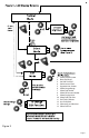
ALDL Harness HN0390 ALDL Tachometer Cable MG2000 Tachometer 4 5 6 1 2 3 4 5 6 3 2 1 12 11 10 9 8 7 12- pin connector Red White Green Black Violet Pink Blue/ White Not Used Not Used Green/ Black Black Tan/ Blue 4- pin connector Red White Green Black & Sheild Heat Shrink Tubing Black Pin A Pin B Pin C Pin D 5 6 7 8 9 10 11 12 Not Used Not Used Green/ Black Black Tan/ Blue 12 3 4 Heat Shrink Tubing Violet Pink Blue/White Pin 1 Pin 2 Pin 3 Pin 4 Pin 5 Pin 6 Pin 7 Pin 8 Pin 9 Pin 10
Harness HN0390 Speedometer Cable MG2000 Speedometer 4 5 6 1 2 3 4 5 6 3 2 1 12 11 10 9 8 7 12- pin connector Pin 1 Pin 2 Pin 3 Pin 4 Pin 5 Pin 6 Pin 7 Pin 8 Pin 9 Pin 10 Pin 11 Pin 12 Red White Green Black Not Used Tan/ Black Tan Not Used Not Used Not Used Not Used Not Used Not Used Not Used Not Used Not Used Not Used Air Temp/ Paddlewheel sender Red (+V) Tan Tan/Black Wire Jacket Not Used 1 2 3 4 5 6 7 8 9 10 11 12 Green (Signal) Bare (Ground) Not Used Not Used White (Thermist
NMEA 2000 Harness HN0401 NMEA 0183 Cable MG2000 Tachometer 4 5 6 11 10 9 8 7 1 12 2 3 6 3 2 5 1 4 6- pin connector Pin 1 Pin 2 Pin 3 Pin 4 Pin 5 Pin 6 Not Used Not Used Red/ White Red/ Blue Not Used Not Used GPS100 Antenna Red/ White Red/ Blue 4 3 Heat Shrink Tubing NMEA 0183-A Red (Ignition) Green (0183-A) Shield (Ground) NMEA 0183-B Not Used Ground *Note: Page 24 Not Used Not Used Brown* White* Yellow* 1) Cut off the connector at the end of the antenna cable 2) Cut off th
Tachometer to 2” Gauge Connection From Tachometer HN0503 4- pin connector Pin A Pin B Pin C Pin D PJ0018 Red White Green Black & Sheild Note: To help reduce moisture in the gauges, be sure to install plug PJ0018 in all open connectors 2" Gauges Page 25
Notes:
Copyright 2005 by the Thomas G. Faria Corporation, Uncasville CT. All rights reserved. No part of this publication may be reproduced in any form, in an electronic retrieval system or otherwise, without the prior written permission of the company. Faria® is the trademark of the Thomas G.