Chapter 3: System Description User Console Version A3.
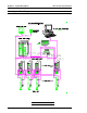
Chapter 3: System Description 3.1 User Console Version A3.53 System Block Diagram FIG.
Chapter 3: System Description User Console Version A3.53 3.1.1 System Block Diagram Description { The System construction provides control for up to 24 spindles through the use of a single Main Controller Unit. { Communication between the Main Controller Unit and up to 24 Axis Controller Units is accomplished via a communication bus ribbon cable (MA/AA cable).
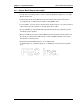
Chapter 3: System Description 3.2 User Console Version A3.53 Component Description 3.2.1 Keypad Unit The keypad provided with the AFC1200 system is utilized for data entry as related to system setup and operation. The cable length is restricted to 1.5 meters. FIG. 3-2-1 Keypad Unit KEYPAD CONTROLS KEY FUNCTION DESCRIPTION HLP Depressing the HLP key will initiate the display of a context sensitive help screen for the current display screen.
Chapter 3: System Description User Console Version A3.53 3.2.2 Monitor (VGA CRT) FEC provides a color VGA monitor (CRT) as part of the standard configuration. The monitor serves to display fastening presets, fastening results, torque signature, and all other information relating to System operation.
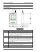
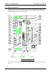
Chapter 3: System Description User Console Version A3.53 3.2.3 Main Controller Unit The Main Unit is composed of an FCBUS mother board, a 5 VDC 10A power supply, and the FC386, MULTI, and UPC printed circuit boards (PCB). The UPC PCB contains the floppy disk drive (FDD) and the hard disk drive (HDD). FIG. 3-2-3 Main Controller Unit The following table describes the components and features of the Main Controller Unit, shown above.
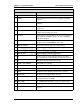
Chapter 3: System Description User Console Version A3.53 MAIN CONTROL UNIT CONTROLS AND INDICATORS Item as called out on Figure 3.2.3 Description 1 RS232C CH1 DSUB 9-pin male RS232C output connector. 2 ACCEPT Display light that indicates when an acceptable fastening is complete. 3 REJECT Display light that indicates when an unacceptable fastening is complete. 4 BUSY Display LED (Orange) that indicates when the fastening cycle is in process.
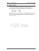
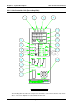
Chapter 3: System Description User Console Version A3.53 3.2.4 Axis Controller Unit (Servo Amplifier) FIG. 3-2-4 Axis Controller Unit The following table describes the components and features of the Axis Controller Unit, shown above. The Servo Amplifier is located inside the Axis Unit.
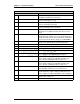
Chapter 3: System Description User Console Version A3.53 AXIS UNIT CONTROLS AND INDICATORS ITEM AS MARKED ON UNIT DESCRIPTION (REFERENCE FIGURE 3-2-4) 1 CHECK Display LED (orange) that indicates when the system is performing a Cal Check or Zero Check. 2 1ST Display LED (orange) that indicates when the fastening cycle is performing the 1st step. 3 FNL Display LED (orange) that indicates when the fastening cycle is performing the final steps.
Chapter 3: System Description User Console Version A3.53 The information displayed in DSP 1 and DSP 2 on the Axis Unit is determined by the Main Controller Unit's AXIS-DSP rotary switch setting. The two display outputs for each switch setting are shown below.
Chapter 3: System Description User Console Version A3.53 3.2.5 Nutrunner (Tool) Unit FIG. 3-2-5 Nutrunner (Tool) Unit { ENCODER P Environmentally isolated angle encoder. P Provides feedback for speed regulation to Servo Amplifier. P Provides angle monitoring capability to fastening operation. { MOTOR P Totally enclosed DC permanent magnet motor. P Refer to Chapter 2 for various motor sizes. { TRANSMISSION P Planetary gear transmission. P Available in straight and offset models.
Chapter 3: System Description User Console Version A3.53 3.2.6 PRBU-DFT Unit (Preamplifier Cable Extender) P This unit can extend the preamplifier cable of the DFT tool up to 100 feet. P The maximum length of the preamplifier cable without this unit is 50 feet. P An external power supply is not required for this unit. P Figure 3-2-6 below illustrates the Unit dimensions (in millimeters), and the recommended positioning of the Unit within the system. CABLE LENGTH: 50' MAX. CABLE LENGHT: 50' MAX.