
Instruction Manual

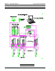
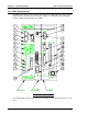

3.1.1 System Block Diagram Description
{ The System construction provides control for up to 24 spindles through the use of a single
Main Controller Unit.
{ Communication between the Main Controller Unit and up to 24 Axis Controller Units is
accomplished via a communication bus ribbon cable (MA/AA cable).
{ Tool assemblies connect to their respective Axis Controller Units via a set of three homerun
cables: Motor, Encoder, and Sensor / Preamp (Transducer) cables.
{ A color VGA CRT (or optional LCD) and keypad provide the interface required to monitor
and adjust System operations.
{ Discrete 24 VDC true low I/O on both the Main Controller Unit and the Axis Controller Unit
provide direct communications with the PLC, as well as individual spindle control via the
Axis Controller Unit discrete I/O.
{ Communication with additional devices is accomplished via:
(1) RS232 input port, (1) RS232 output port, (1) RS422 port, and (1) Centronics parallel
port.
Chapter 3: System Description User Console Version A3.53
Page 3-3