
Instruction Manual
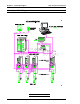
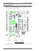
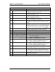

200~230 VAC +/- 10%, 50/60 Hz, single phase input power
connector.
AC200~230V22
DSUB 25-pin female Centronics parallel port connector.PRINTER21
3.5" 1.44MB Floppy Disk Drive (notebook computer style).FDD1 / FDD220
2" IDE Hard Disk Drive (notebook computer style). Size may
vary dependent upon availability.
HDD1 (INSIDE - NOT VISIBLE)19
DSUB 9-pin male RS232C input connector.RS232C CH218
DSUB 9-pin female RS422 communications connector.RS42217
DSUB 15-pin female VGA CRT connector.CRT16
Connector for optional Liquid Crystal Display (LCD).LCD15
Backup battery (3-year life).(INSIDE - NOT VISIBLE)14
MINI DIN 6 pin keyboard/keypad connector.K/B13
Interface connector for System input/output control lines.
Refer to Chapter 4 for detailed input and output descriptions.
PLC12
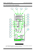
Manual Calibration (Cal) Check pushbutton.(MANUAL) CAL11
Manual reverse pushbutton.(MANUAL) REV10
Manual fastening start pushbutton. (MANUAL) START9
Manual Zero Check and System reset pushbutton.(MANUAL) RESET8
Operating mode selector (key) switch. Set to RUN for normal
operation, and set to PROGRAM to enter data.
RUN / PROGRAM7
Rotary switch for selecting which items are to be displayed at
Axis Unit DSP1 and DSP2. (Refer to the Axis Unit Display
Table in this Chapter)
AXIS-DSP6
Display LED (Orange) that indicates when either a Cal Check
or a Zero Check is being performed.
CHECK 5
Display LED (Orange) that indicates when the fastening cycle
is in process.
BUSY 4
Display light that indicates when an unacceptable fastening is
complete.
REJECT 3
Display light that indicates when an acceptable fastening is
complete.
ACCEPT 2
DSUB 9-pin male RS232C output connector.RS232C CH11
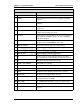
DescriptionItem as called out on Figure 3.2.3
MAIN CONTROL UNIT CONTROLS AND INDICATORS
Chapter 3: System Description User Console Version A3.53
Page 3-7