
Instruction Manual
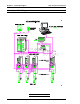
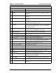
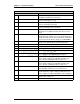

200~230 VAC, 50/60 Hz, 3-phase input power connector.AC-POWER 18
Six (6) dual-color LED indicators. Refer to Axis Unit Reject
Display Table on Page 3-11.
REJECT 17
Displays two-digit Parameter number and, as needed, will
override Parameter output to display an Abnormal code.
Refer to Chapter 9 for Abnormal display code descriptions.
PARM/ABN16
Two-digit capability, Spindle number display. Determined
by the dip switch setting (reference Section 4.9.1).
SPDL15
Type of information displayed is dependent upon the
selector switch setting on the ISA Main Controller Unit.
Refer to the Axis Unit Display Table on Page 3-11.
DSP 214
Type of information displayed is dependent upon the
selector switch setting on the ISA Main Controller Unit.
Refer to the Axis Unit Display Table on Page 3-11.
DSP 113
Axis Unit input / output control lines (PLC) connector.
Refer to Chapter 4 for detailed signal descriptions.
AXIS-I/O12
Connector for the nutrunner (tool) motor (M).MOTOR11
Connector for the nutrunner (tool) encoder (ENC).ENCODER10
Connector for the tool torque transducer/preamplifier (PA).SENSOR9
Axis Unit enable / disable switch.NORMAL / IN BYPASS8
Display LED (red) that indicates when the Axis Unit is in the
Bypass mode. Spindle will not operate in this mode.
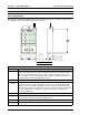
BYPASS 7
Display LED (red) that indicates some component of the
spindle (Axis Unit, nutrunner, etc.) is in an Abnormal state,
and the fastening cycle has been interrupted. A failed Cal
Check or Zero Check will also display as an ABNORMAL.
ABNORMAL6
Display LED (green) that indicates the spindle has
completed an acceptable fastening, Zero Check, or Cal
Check.
ACCEPT 5
Display LED (orange) that indicates when the fastening
cycle is performing a reverse operation.
REV4
Display LED (orange) that indicates when the fastening
cycle is performing the final steps.
FNL 3
Display LED (orange) that indicates when the fastening
cycle is performing the 1st step.
1ST 2
Display LED (orange) that indicates when the system is
performing a Cal Check or Zero Check.
CHECK1
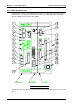
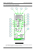
DESCRIPTION (REFERENCE FIGURE 3-2-4) ITEM AS MARKED ON UNIT
AXIS UNIT CONTROLS AND INDICATORS
Chapter 3: System Description User Console Version A3.53
Page 3-9