Chapter 8: Maintenance and Inspection User Console Version A3.
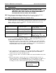
Chapter 8: Maintenance and Inspection 8.1 User Console Version A3.53 Inspection Items A scheduled inspection is recommended to keep the AFC1200 System in the best condition. A preventive maintenance routine should be practiced monthly. WARNING: Follow Lockout/Tagout and other safety precautions when connecting or disconnecting cabling, wiring, and equipment. Always verify the System is disabled prior to touching any moveable components. 8.1.
Chapter 8: Maintenance and Inspection User Console Version A3.53 8.1.5 Axis Controller unit As with the Main Unit, the Axis Unit requires careful use and handling. Inspect each Axis Unit and ensure the following requirements are met: w The environmental conditions are within specifications. w There is no dust, oil, or foreign matter on the Unit. w The Unit is securely mounted, with appropriate clearance on all sides. w All screws (for the cover of the Unit and for mounting) are correctly tightened.
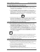
Chapter 8: Maintenance and Inspection 8.2 User Console Version A3.53 Basic operational tests WARNING: Follow Lockout/Tagout and other safety precautions when connecting or disconnecting cabling, wiring, and equipment. When performing the following inspections, verify that the System is disabled prior to touching any moveable components. 8.2.1 Torque transducer The System performs a transducer check before each fastening cycle (when selected by the PLC or Sequence Setup).
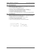
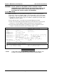
Chapter 8: Maintenance and Inspection User Console Version A3.53 8.2.3 Nutrunner (Tool) Motor WARNING: Follow Lockout/Tagout and other safety precautions when connecting or disconnecting cabling, wiring, and equipment. When performing the following inspections, verify that the System is disabled prior to touching any moveable components. 1. Disconnect the motor homerun cable from the tool motor connector (FIG. 8-2-3). 2. Measure the resistance between windings. Refer to FIG. 8-2-3 and the chart, below. 3.
Chapter 8: Maintenance and Inspection User Console Version A3.53 Motor Winding Resistance* MOTOR SIZE A-B A-C B-C 60W (M1) 12.8Ω 12.8Ω 12.8Ω 70W (W1) 15.3Ω 15.3Ω 15.3Ω 100W (M2) 4.4Ω 4.4Ω 4.4Ω 200W (M3) 2.1Ω 2.1Ω 2.1Ω 200W (W3) 4.0Ω 4.0Ω 4.0Ω 400W (M4) .7Ω .7Ω .7Ω Rev. 1/08/01 INSULATION Resistance MOTOR SIZE A-D B-D C-D 60W (M1) 70W (W1) 100W (M2) More than 50 megohms at 500 VDC 200W (M3) 200W (W3) 400W (M4) 8.2.
Chapter 8: Maintenance and Inspection User Console Version A3.53 transmission housing with excessive grease; overgreasing could damage the tool. Recommended grease: Sunoco Sunaplex 992 EP or equivalent. 6. REASSEMBLE TRANSMISSION. Refer to the appropriate transmission assembly drawing while reassembling the transmission. If needed, rotate the gears to aid in the assembly process.
Chapter 8: Maintenance and Inspection 8.3 User Console Version A3.53 Replacements WARNING: DO NOT CONNECT OR DISCONNECT CABLES OR OTHER SYSTEM COMPONENTS WITH POWER APPLIED. FOLLOW LOCKOUT/TAGOUT AND OTHER APPLICABLE SAFETY PRECAUTIONS WHEN CONNECTING OR DISCONNECTING CABLING, WIRING, AND EQUIPMENT. NOTE: When replacing the AFC1200 System Main Controller Unit, ensure that the new Unit is configured with the same hardware and software as the Unit being replaced. 8.3.
Chapter 8: Maintenance and Inspection User Console Version A3.53 8.3.2 MULTI PCB Replacement (Part of Main Unit) Replace the AFC1200 System Main Unit MULTI PCB as follows: 1. Ensure that the power is off. Remove any component cables connected to the PCB. Remove the four (4) screws holding the board face plate (on front of Main Unit), and pull out straight to remove the MULTI PCB. 2.
Chapter 8: Maintenance and Inspection User Console Version A3.53 WARNING: DO NOT CONNECT OR DISCONNECT CABLES OR OTHER SYSTEM COMPONENTS WITH POWER APPLIED. FOLLOW LOCKOUT/TAGOUT AND OTHER APPLICABLE SAFETY PRECAUTIONS WHEN CONNECTING OR DISCONNECTING CABLING, WIRING, AND EQUIPMENT. 8.3.5 CMOS Setup CMOS setup will have to be performed if the battery fails or is removed, if the System configuration is changed (new HDD or FDD), or if the FC386 PCB is replaced.
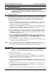
Chapter 8: Maintenance and Inspection User Console Version A3.53 COMMONLY USED DRIVE TYPES MODEL TYPE CYL. HD. PRE. SEC. SIZE CP2124 CP2174 CP2254 CFN250A CFL350A ST-9420AG WDAL2540 47 48 48 48 48 48 48 763 326 489 489 905 988 1,048 8 16 16 16 12 16 16 1,023 1,023 1,023 1,023 1,023 1,023 1,023 39 63 63 63 63 52 63 116 MBYTE 160 MBYTE 240 MBYTE 240 MBYTE 333 MBYTE 400.9 MBYTE 540.8 MBYTE Chips and Technologies, Inc.
Chapter 8: Maintenance and Inspection User Console Version A3.53 Chips and Technologies, Inc. System Configuration Utility 82C711 CONFIGURATION Disable Manual Override: FDC Interface: IDE Interface: Primary Serial Port: Secondary Serial Port: Primary Serial Address: Secondary Serial Address: Parallel Port: Parallel Port Mode: Enabled Enabled Enabled Enabled COM1, 3F8H COM2, 2F8H 278H Printer ←↑→↓ to select entries PgUp for Advanced Feature Control + and - to change an entry.
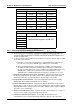
Chapter 8: Maintenance and Inspection User Console Version A3.53 WARNING -- Improper use of certain CHIPSet REGISTER CONTROL selections may cause the system to fail or behave unpredictably. If the System fails, turn it off and then on. The System will detect that a failure has occurred and will use default CHIPSet values. Press the ENTER key to continue into CHIPSet REGISTER CONTROL. ←↑→↓ to select entries PgUp/PgDn to change menu + and - to change an entry.
Chapter 8: Maintenance and Inspection User Console Version A3.53 5. Follow all safety precautions to install the UPC PCB in reverse order of removal. 6. Verify that power is off, and disconnect any component cables connected to the FC386 PCB. Remove the two (2) screws holding the FC386 PCB face plate (on front of the Main Unit), and pull out straight to remove the PCB. 7. Locate the RDISK daughter board installed at the approximate center of the FC386 PCB.
Chapter 8: Maintenance and Inspection Note: User Console Version A3.53 Although "A" type Axis Units (AXIS-203A, for example) accomodate the same nutrunners as their older style counterparts, they are not fully interchangeable. REPLACE OLDER STYLE AXIS UNITS WITH THE SAME, AND REPLACE THE "A" TYPE UNITS WITH OTHER "A" TYPE UNITS. If it is necessary to intermix older style Units with "A" type Units, contact FEC INC. for guidance.
Chapter 8: Maintenance and Inspection User Console Version A3.53 8.3.10 Replace nutrunner (tool) Do not attempt to replace a component of the tool - the tool must be replaced as a complete assembly. The tool type identification can be found on the identification tag affixed to the tool and on the System [PREAMP EEPROM DATA] screen. WARNING: DO NOT CONNECT OR DISCONNECT CABLES OR OTHER SYSTEM COMPONENTS WITH POWER APPLIED. 1. Verify all System power is off. 2.