
User Manual


WARNING:
DO NOT CONNECT OR DISCONNECT CABLES OR OTHER SYSTEM
COMPONENTS WITH POWER APPLIED. FOLLOW LOCKOUT/TAGOUT AND
OTHER APPLICABLE SAFETY PRECAUTIONS WHEN CONNECTING OR
DISCONNECTING CABLING, WIRING, AND EQUIPMENT.
8.3.5 CMOS Setup
CMOS setup will have to be performed if the battery fails or is removed, if the System
configuration is changed (new HDD or FDD), or if the FC386 PCB is replaced. The CMOS
setup is similar to that of any IBM-compatible system, and should be performed as follows:
1. An IBM PS/2-compatible full-size keyboard or IBM AT-compatible keyboard with a DIN -
MINI DIN converter is required.
2. Ensure that the power is off, and disconnect the AFC1200 keyboard cable.
3. Power on the System with the keyboard disconnected. A keyboard error message will
prompt you to select the CMOS configuration SETUP by pressing the [F2] key.
4. Reconnect the keyboard and depress the [F2] key for the first configuration screen.
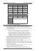
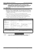
Complete setup using information from the following sample screens.
F10 to save then exitESC to exit without saving
PgDn for Advanced Feature Controland +/- to change an entry.
Use cursor arrows to select entries
EGA or VGADisplay:
1024 KB1024 KBExtended Memory:
640 KB640 KBBase Memory:
BIOS found:
Not installedFixed Disk D:
116 39763none 8 762Type 47
Fixed Disk C:**
SizeSecLZPreHdCyl
Not installed
Diskette B:**
3.5 Inch,1.44 MB
Diskette A:**
Coprocessor:May 06, 1992Date:
Processor:16:14:09Time:
STANDARD SETUP OPTIONS
Chips and Technologies, Inc. System Configuration Utility
FIG. 8-3-4a CMOS Setup page 1
** NOTE: THESE ITEMS ARE SET ACCORDING TO WHAT IS INSTALLED INTO THE
SYSTEM. ALL OTHERS ARE SET AS DISPLAYED IN THESE TABLES.
Chapter 8: Maintenance and Inspection User Console Version A3.53
Page 8-10