Chapter 9: Troubleshooting Chapter 9: Troubleshooting Page 9-1
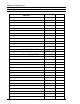
Chapter 9: Troubleshooting 9.0 Alphabetical List of Abnormals MONITOR (CRT) DISPLAY "ABNORMAL" MESSAGE Axis Unit Abnormal Codes SECTION # PAGE # 9.6 9-26 Axis Unit Lockout (actual lockout - not a display) 9.4.16 9-24 Cal Check Abnormal 9.4.2 9-16 CMOS Power On Self-Test (POST) Failure 9.1.3 9-4 Command Error 9.2.1 9-7 Communications Time Over 9.2.10 9-10 Communications I/F Abnormal 9.1.1 9-4 Console Dual Port Ram Abnormal 9.3.9 9-14 Controller EEPROM Write Abnormal 9.3.
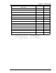
Chapter 9: Troubleshooting MONITOR (CRT) DISPLAY "ABNORMAL" MESSAGE Run Mode SECTION # PAGE # 9.2.9 9-10 Selected Sequence Does Not Exist 9.3.5 9-13 Servo I/F Power Supply Abnormal 9.4.14 9-23 Servo Type Abnormal 9.4.15 9-23 Servo Alarm 9.4.8 9-19 Spindle Download Error 9.2.6 9-9 Spindle Communication I/F Abnormal 9.3.6 9-13 Spindle Dual Port RAM Abnormal 9.3.1 9-11 Sub Command Error 9.2.1 9-7 System Config Set Abnormal 9.3.8 9-14 Tool Is Not Connected 9.4.
Chapter 9: Troubleshooting 9.1 POWER ON ABNORMAL WARNING: DO NOT CONNECT OR DISCONNECT CABLES OR OTHER SYSTEM COMPONENTS WITH POWER APPLIED. Communications I/F Abnormal CMOS Power On Self-Test (POST) Failure DOS Boot Failure Keyboard Failure CRT Failure Failure to Fasten 9.1.1 COMMUNICATIONS I/F ABNORMAL THE Processor PCB did not communicate properly with the MULTI2 PCB during the power on initialization of the System. 1.
Chapter 9: Troubleshooting WARNING: DO NOT CONNECT OR DISCONNECT CABLES OR OTHER SYSTEM COMPONENTS WITH POWER APPLIED. 9.1.4 CRT Failure THE Monitor (VGA CRT) is not displaying anything during and after System initialization. 1. depress any key on the keypad to ensure that the screen saver is not active. 2. verify that the CRT power on switch is in the ON position. 3. Verify that the CRT, input power, and Main Unit VGA output connections are correct. 4.
Chapter 9: Troubleshooting WARNING: DO NOT CONNECT OR DISCONNECT CABLES OR OTHER SYSTEM COMPONENTS WITH POWER APPLIED. 9.1.6 Failure to fasten THE System power on initialization is completed, but the System is not responding to fastening commands from the station control. 1. Check for Abnormal indicators or messages. If an Abnormal is present, then reference the appropriate Section of Chapter 9, correct the Abnormal, and attempt to fasten again. 2.
Chapter 9: Troubleshooting 9.2 cOMMUNICATION ABNORMAL WARNING: DO NOT CONNECT OR DISCONNECT CABLES OR OTHER SYSTEM COMPONENTS WITH POWER APPLIED. COMMAND ERROR PRESETTING ERROR UPlOAD ERROR SPinDLe DOWNLOAD ERRor NO STATISTICS DATA COMMUNicationS TIME OVER SUB COMMAND ERROR FASTENING NO UPlOAD DATA EEPROM WRITE ERROR RUN MODE 9.2.
Chapter 9: Troubleshooting WARNING: DO NOT CONNECT OR DISCONNECT CABLES OR OTHER SYSTEM COMPONENTS WITH POWER APPLIED. 9.2.3 FASTENING AN attempt was made to change the pREset data during the fastening process. 1. Verify that the Machine is not busy performing a fastening cycle. 2. Place the RUN / PROGRAM switch into the Program position. Enter the desired data, then place the switch back into the Run position. 3.
Chapter 9: Troubleshooting WARNING: DO NOT CONNECT OR DISCONNECT CABLES OR OTHER SYSTEM COMPONENTS WITH POWER APPLIED. 9.2.6 SPINDLE DOWNlOAD ERROR PReset data was not downloaded during communication between the Multi2 PCB and the AXIS UNIT. 1. Ensure that the ISA Main Unit and the Axis Unit(s) are correctly connected to the communication bus ribbon cable. 2. ENTEr the preset data required for the specified screen. 3.
Chapter 9: Troubleshooting COMPONENTS WITH POWER APPLIED. 9.2.9 RUN MODE An attempt was made to change System data or presets with the ISA Main Unit set to the Run mode. 1. Verify that the System is not busy performing a fastening cycle. 2. Place the Run / Program switch on the ISA Main Unit into the Program position. Enter the desired data, then set the switch back into the Run position. 3.
Chapter 9: Troubleshooting 9.3 coNTROLLER ERROR WARNING: DO NOT CONNECT OR DISCONNECT CABLES OR OTHER SYSTEM COMPONENTS WITH POWER APPLIED. SPINDLE DUAL PORT RAM ABNORMAL ABNORMAL PRESET SPINDLE DOES NOT EXIST ABNORMAL SELECTED SEQUENCE DOES NOT EXIST ABNORMAL PARAMETER SET ABNORMAL ABNORMAL CONSOLE DUAL PORT RAM ABNORMAL PREAMP EEPROM READ CONTROLLER EEPROM WRITE SPINDLE COMMUNICATION I/F SYSTEM CONFIG SET 9.3.
Chapter 9: Troubleshooting 3. Verify that the homerun cable is in good condition and is properly connected to both the Axis Unit and the tool (preamp / sensor). 4. ensure that the ISA Main Unit and the Axis Unit are not located near any strong electrical or magnetic fields. 5. Verify that the input power specifications (200~230 VAC +/- 10%, 50/60 Hz) are met for both the Axis Unit (3-phase) and the ISA Main Unit (single phase). 6.
Chapter 9: Troubleshooting 2. Re-enter the data on the MACHINE CONFIGURATION / SET SEQUENCE / SET PARAMETER screens (or reload the Preset files from the PRESET FILE UTILITY screen). 3. ensure that the ISA Main Unit is not located near any strong electrical or magnetic fields. 4. Confirm that the ISA Main Unit input power remains constantly within specifications: 200~230 VAC +/- 10%, 50/60 Hz, single phase. 5. Verify that the ISA Main Unit power cable is free from damage and is properly connected. 6.
Chapter 9: Troubleshooting 6. If the problem still exists, replace the affected AXIS UNit. (Refer to Section 8.3.3) 7. If the problem persists, replace the entire ISA Main Unit. (Refer to Section 8.3.1) WARNING: DO NOT CONNECT OR DISCONNECT CABLES OR OTHER SYSTEM COMPONENTS WITH POWER APPLIED. 9.3.7 PARAMETER SET ABNORMAL Fastening presets are set-up incorrectly. 1.
Chapter 9: Troubleshooting 2. Confirm that the ISA Main Unit input power remains constantly within specifications: 200~230 VAC +/- 10%, 50/60 Hz, single phase. 3. Verify that the ISA Main Unit power cable is free from damage and is properly connected. 4. If the problem persists, replace the entire ISA Main Unit. (Refer to Section 8.3.
Chapter 9: Troubleshooting 9.4 AXIS UNIT ABNORMAL WARNING: DO NOT CONNECT OR DISCONNECT CABLES OR OTHER SYSTEM COMPONENTS WITH POWER APPLIED.
Chapter 9: Troubleshooting 7. If the problem persists, replace the affected AXIS UNit. (Refer to Section 8.3.
Chapter 9: Troubleshooting WARNING: DO NOT CONNECT OR DISCONNECT CABLES OR OTHER SYSTEM COMPONENTS WITH POWER APPLIED. 9.4.2 CAL CHECK ABNORMAL ( axis Unit display code "a1" ) the Calibration (Cal) level of the tool transducer is outside of the acceptable limits. The following table details the limits of the check for various equipment conditions. Cal level check at power on. The Cal level must be within ± 0.075 VDC (3% of 2.5 VDC) of the value read from the tool EEPROM.
Chapter 9: Troubleshooting WARNING: DO NOT CONNECT OR DISCONNECT CABLES OR OTHER SYSTEM COMPONENTS WITH POWER APPLIED. 9.4.3 OFFSET CHECK ABNORMAL ( axis Unit display code "a2" ) the Offset (torque level) Check of the tool is outside of the acceptable limits. The following table details the limits of the check for various equipment conditions. Offset torque level check while the PLC Offset Check input is enabled.
Chapter 9: Troubleshooting 4. Verify that the communication bus ribbon cable is in good condition and is properly connected to both the MAIN UNIt and the AXIS UNIT. 5. ensure that the ISA Main and Axis Units are not located near any strong electrical or magnetic fields. 6. Verify that the input power specifications (200~230 VAC +/- 10%, 50/60 Hz) are met for both the Axis Unit (3-phase) and the ISA Main Unit (single phase). 7. Verify that all power cables are in good condition and are properly connected. 8.
Chapter 9: Troubleshooting malfunctioning Axis Unit. If all Axis Units appear to be functional, the problem is likely to be found in another System component. 3. if the problem affects only a single spindle, check the affected spindle for binding and excessive prevailing torque. If either condition is found, isolate and correct the cause. 4. If no binding or excessive prevailing torque is found, verify correct Axis Unit input voltage and ensure that the power cable is properly connected. 5.
Chapter 9: Troubleshooting 3. If the problem appears to be a common fault, verify correct input power to the Axis Units. 4. if the problem only affects a single spindle, check the affected spindle for binding and excessive prevailing torque. If either condition is found, isolate and correct the cause. 5. If no binding or excessive prevailing torque is found, verify correct Axis Unit input voltage and ensure that the power cable is properly connected. 6.
Chapter 9: Troubleshooting WARNING: DO NOT CONNECT OR DISCONNECT CABLES OR OTHER SYSTEM COMPONENTS WITH POWER APPLIED. 9.4.9 FULL SCALE TORQUE OVER ABNORMAL (axis Unit display code "a1") MEasured torque exceeded full scale (CALIBration) torque. 1. Verify that the tool is properly secured to the mounting plate, and that there is no sign of stress or misalignment. Ensure that there is no tool movement while the self-check is being performed. 2. Turn off the power.
Chapter 9: Troubleshooting WARNING: DO NOT CONNECT OR DISCONNECT CABLES OR OTHER SYSTEM COMPONENTS WITH POWER APPLIED. 9.4.11 tOOL TYPE MISMATCH ABNORMAL (axis Unit display code "a3") PRESet tool type and connected tool type are mismatched. 1. Verify that the MACHINE CONFIGURATION / SET SEQUENCE / SET PARAMETER screens match the physical machine configuration. 2.
Chapter 9: Troubleshooting COMPONENTS WITH POWER APPLIED. 9.4.13 input power over abnormal (axis Unit display code "d5, d6") the input power exceeds specifications (200~230 VAC ± 10% , 50/60 Hz). When this error message is displayed on the CRT, the corresponding Axis Unit display should be checked for an Abnormal code. Refer to Section 9.6 for more information regarding this failure type. D5/input voltage abnormal (high) errors D6/input voltage abnormal (low) errors 1.
Chapter 9: Troubleshooting 8. Verify that all power cables are in good condition and are properly connected. 9. If the problem still exists, replace the affected AXIS UNit. (Refer to Section 8.3.3) 10. If the problem persists, replace the affected tool. (Refer to Section 8.3.4) WARNING: DO NOT CONNECT OR DISCONNECT CABLES OR OTHER SYSTEM COMPONENTS WITH POWER APPLIED. 9.4.
Chapter 9: Troubleshooting 9.5 INPUT aBNORMAL 9.5.1 INPUT ERROR INPUT data has been entered in an incorrect format. 1. DATA will display, but will not update. Enter the data in the correct format. 9.5.2 DATA ERROR INput data has been entered that is beyond the limits of the existing configuration. 1. DATA will display, but will not update. Enter data that is within acceptable limits.
Chapter 9: Troubleshooting 9.6 Axis Unit Abnormal codes 9.6.1 AXis Unit Control abnormals CODE / "ABNORMAL" TYPE DESCRIPTION A1 ZERO CHECK, CAL CHECK, AND FULL SCALE TORQUE OVER ABNORMALS Review the abnormal display on the system CRT to determine whether the Abnormal condition is from a "Zero Check Abnormal", "Cal Check Abnormal", or "Full Scale Torque Over Abnormal". Refer to Section 9.4.1 for a Zero Check Abnormal. Refer to Section 9.4.2 for a Cal Check Abnormal. Refer to Section 9.4.
Chapter 9: Troubleshooting 9.6.2 axis unit servo drive abnormals CODE / "ABNORMAL" TYPE DESCRIPTION D0 ENCODER CONNECTION ABNORMAL This Abnormal occurs if the tool encoder circuit is not properly connected or is not working properly. Refer to Sections 9.4.5. and 9.4.8. D1 TOOL / SERVO MISMATCH If this Abnormal occurs during power on, the tool type and servo (Axis Unit) type do not match. Refer to Section 9.4.8. D2 ENCODER ABNORMAL Abnormal condition occurred in the tool angle encoder signal.
Chapter 9: Troubleshooting 9.7 file error messages for disk drive operations ERROR MESSAGE DEFINITION DOS DRIVE ERROR 01H INVALID FUNCTION WAS SELECTED. DOS DRIVE ERROR 02H NO SELECTED FILE EXISTS. DOS DRIVE ERROR 03H NO PATH EXISTS. TOO MANY FILES OPEN TOO MANY FILES OPEN. DOS DRIVE ERROR 05H ACCESS WAS DENIED. DOS DRIVE ERROR 06H INVALID HANDLING. DOS DRIVE ERROR 07H INDEX DATA WERE BROKEN. DOS DRIVE ERROR 08H NOT ENOUGH MEMORY. DOS DRIVE ERROR 09H INVALID MEMORY WAS SELECTED.
Chapter 9: Troubleshooting 9.8 AFC1200 Axis Unit Fastening Faults and Causes 9.8.1 Accept Conditions THE ACCEPT LED will light for the three following reasons: 1. tHE RESET input is active on either the front panel or via a PLC input, and the reset condition (ZERO LEVEL) of the TRANSDUCER is within acceptable limits. 2. tHE CAL input is active on either the front panel or via a PLC input, and the calibration condition (CAL LEVEL) of the transducer is within acceptable limits. 3.
Chapter 9: Troubleshooting CAUSES: REDuced lubrication, thread obstacle, reduced joint compression. 9.8.4 TIME REJECT conditions THe TIMe Reject LED will light for the following reasons: 1. A "RED" TIme Reject LED on the AXIS Unit indicates a Final step Time Reject. 2. An "ORANGE" TIme Reject LED on the AXIS Unit indicates a 1st step TIme Reject. May cause a LOW TOrque Reject. CAUSES: 1. THE amount of time specified on the Parameter Set screen is insufficient. 2.
Chapter 9: Troubleshooting CAUSES of LOW RATe Rejects: EXcessive lubrication, thread obstacle, excessive joint compression.