Chapter 3: System Description PAGE 3 - 1
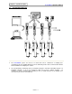
Chapter 3: System Description 3.1 enFORCE Operation Manual System Block Diagram ♦ The enFORCE system can consist of a stand alone unit or combined in a multiple press configuration. Discrete 24VDC (Sinking) I/O on the SAN unit provides direct communication with the PLC for individual or multiple press control.
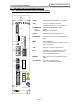
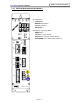
Chapter 3: System Description enFORCE Operation Manual 3.2 DSP1500 Front Panel (enFORCE Controller) 3.2.1 DSP1500 Front Panel Switches and Connectors DSP1500 CON1 SW1 POWER CON1: For Display Unit (SAN-DP*S) connection. SW1: Sets press number and special configuration features.(See Section 4.8) RUN/BYPASS: RUN: BYPASS: Controller Enable/Disable switch. Enable Bypass Mode(Disable) RS485: Bi-directional Communication ports. RESOLVER: Resolver connection for tool Motor/Resolver cable. MON.
Chapter 3: System Description enFORCE Operation Manual 3.2.2 DSP1500 Front Panel Condition Display LED’s DSP1500 POWER LED (Yellow) Lights when 180~242VAC input power is applied to the controller. CON1 SW1 POWER BUSY SV. BYPASS RUN BUSY LED (Orange) Lights up when in cycle Blinks when returning Blinks when running in MANUAL Lights up when powering on and initializing ABN. ACC. REJ . RS 485 SV. [SERVO] LED (Red) Lights up when a servo amplifier fault condition exists. ABN.
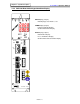
Chapter 3: System Description enFORCE Operation Manual 3.2.3 DSP1500 Detachable Keypad Buttons START MANUAL CAL ( SEARCH) RESET Operating Button START Button MANUAL Mode Button CAL Manual Button RESET Button DATA DSP1500 D-NO PARM MODE DATA SET ( HOME) BYPASS RUN Data Display / (Operating) Button MODE Button SET Button(Home Return) DATA UP Cursor Button(Manual Return) DATA DOWN Cursor Button (Manual Advance) ABN. ACC. REJ . RS 485 RESOLVER MON.
Chapter 3: System Description enFORCE Operation Manual 3.2.4 DSP1500 Detachable Keypad Condition Display START MANUAL CAL ( SEARCH) RESET DATA Display (4 figure) Data Display (Load, Distance, etc.) DATA PARM Display (2 figure) Parameter Number Display Or Abnormal Number Display DSP1500 D-NO PARM MODE DATA SET ( HOME) BYPASS RUN D-NO Display (2 figure) Data Number Display Press Unit Number Display Or Abnormal Sub-Code Number Display ABN. ACC. REJ . RS 485 RESOLVER MON.
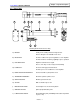
Chapter 3: System Description enFORCE Operation Manual 3.3 Press Tool Drawing Shown For Reference Only A) MOTOR: Totally enclosed DC permanent magnet motor Refer to Chapter 2 for available motor sizes B) RESOLVER: Provides feedback for speed regulation to servo amplifier Provides distance monitoring capability to press operation C) PRE-AMPLIFIER: Amplifies load transducer signal. Houses “I.D.
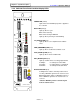
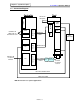
Chapter 3: System Description enFORCE Operation Manual 3.4 Connection Diagram Controller Tool TO PLC OR I/O DEVICE CON1 BRAKE BRAKE CABLE MOTOR ※ CCW *ORG RESOLVER CABLE RES. RS485 RESOLVER RS485 CONNECT TO COMPUTER, PC OR NEXT SAN UNIT LOAD CELL PREAMPLIFIER MON MOTOR T/D MOTOR CABLE CW PLC AC 200-220V CONNECT TO PLC OR I/O DEVICES INPUT POWER Noise Circuit filter protector CABLE I/O & LIMIT SENSOR CABLE LOAD CELL CABLE *ORG Connection is for special applications.