OPERATOR’S MANUAL IS5000Z Series Zero-Turn Riding Mower Tractor Serial No. 1226 & above Mower Serial No. 1210 & above Ferris Industries 5375 North Main Street Munnsville, NY 13409 800-933-6175 Tractor: Mower Deck: Model IS5000Z/C31D IS5000Z/C31DCE IS5000ZC31D61CE Model 5000/72 5000/72R 5000/72RCE 5000/61R 5000/61RCE 23458 Revision 00 Rev.
Table of Contents Troubleshooting, Adjustments & Service .......25 Safety Rules & Information ................................2 Identification Numbers .......................................5 Safety Decals & Icons.........................................6 Safety Interlock System......................................7 Features & Controls ............................................8 Troubleshooting the Rider .....................................25 Troubleshooting the Mower .................................
Safety Rules & Information Read these safety rules and follow them closely. Failure to obey these rules could result in loss of control of unit, severe personal injury or death to you, or bystanders, or damage to property or equipment. This mowing deck is capable of amputating hands and feet and throwing objects. The triangle in text signifies important cautions or warnings which must be followed. TRAINING OPERATION 1.
Safety Rules & Information 23. Use care when approaching blind corners, shrubs, trees or other objects that may obscure vision. 24. To reduce fire hazard, keep unit free of grass, leaves & excess oil. Do not stop or park over dry leaves, grass or combustible materials. 25. The engine in this unit is not factory equipped with a spark arrester.
Safety Rules & Information SERVICE AND MAINTENANCE 10. Let engine cool before storing and do not store near flame. 11. Stop and inspect the equipment if you strike an object. Repair, if necessary, before restarting. 12. Park machine on level ground. Never allow untrained personnel to service machine. 13. Use jack stands to support components when required. 14. Carefully release pressure from components with stored energy. 15. Disconnect battery or remove spark plug wire before making any repairs.
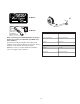
S A M P LE SA Model No.: XXXXXXXXXX kW: XXX Engine RPM: XXXX LpA: XX dB(A) Vibration @ Wheels: XXX Vibration @ Seat: XXX M 200X PL XXX E Ferris Industries, Inc. Munnsville, NY USA 13409 All Models CE Models PRODUCT XXX When contacting your authorized dealer for replacement parts, service, or information you MUST have these numbers. Record your model/serial number and engine serial numbers on the space provided for easy access.
SAFETY DECALS This unit has been designed and manufactured to provide you with the safety and reliability you would expect from an industry leader in outdoor power equipment manufacturing. Although reading this manual and the safety instructions it contains will provide you with the necessary basic knowledge to operate this equipment safely and effectively, we have placed several safety labels on the unit to remind you of this important information while you are operating your unit.
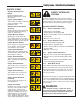
Safety Icons / Identification Numbers SAFETY ICONS SAFETY INTERLOCK SYSTEM Warning: Read Operator’s Manual. Read and understand the Operator’s Manual before using this machine. This unit is equipped with safety interlock switches. These safety systems are present for your safety, do not attempt to bypass safety switches, and never tamper with safety devices. Check their operation regularly. Danger: Thrown Objects. This machine is capable of throwing objects and debris. Keep bystanders away.
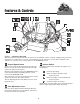
Features & Controls Figure 1. CONTROL FUNCTIONS The information below briefly describes the function of the individual controls. Starting, stopping, driving, and mowing require the combined use of several controls applied in specific sequences. To learn what combination and sequence of controls to use for various tasks see the OPERATION section. Ground Speed Levers Ignition Switch These levers control the ground speed of the rider.
Features & Controls Glow Plug Indicator Indicator Lights & Alarm Indicates that the glow plugs are heating. Holding the ignition key in the “HEAT” position until indicator starts to glow, then turn the key to start. The indicator lights will illuminate and the alarm will sound when the ignition switch is in the “ON” position before cranking the engine.
Operation GENERAL OPERATING SAFETY CHECKS BEFORE STARTING Before first time operation: • Be sure to read all information in the Safety and Operation sections before attempting to operate this tractor and mower. • Check that crankcase is filled to full mark on dipstick. See the engine Operators Manual for instructions and oil recommendations. • Check the radiator fluid level. See engine operator’s manual for instructions. • Become familiar with all of the controls and how to stop the unit.
Operation PRIMING THE FUEL SYSTEM Priming the fuel system fills the fuel filters and removes any air bubbles from the fuel system. This must be performed before the first use, after any fuel filter maintenance or if the fuel system is run dry. To prime the fuel system: On the water separator: 1. Using a 1/2” wrench, loosen the vent screw on the water separator 2-3 revolutions. 2. Unscrew the priming hand pump (B, Figure 3) located on top of the water separator.
Operation STOPPING THE TRACTOR & ENGINE WARNING 1. Returning the ground speed control levers to the middle position will stop tractor movement. Pivot the levers outward and lock them in neutral. If you do not understand how a specific control functions, or have not yet thoroughly read the FEATURES & CONTROLS section, do so now. 2. Disengage the PTO. Do NOT attempt to operate the tractor without first becoming familiar with the location and function of ALL controls. 3. Engage the parking brake. 4.
Operation MOWING 1. Engage the parking brake. Make sure the PTO switch is disengaged, the motion control handles are locked in the NEUTRAL position and the operator is on the seat. 2. Start the engine (see STARTING THE ENGINE). 3. Set the mower cutting height. 4. Set the throttle to FULL. 5. Engage the PTO by pulling up on the PTO switch. 6. Begin mowing. See the Lawn Care Section for tips on mowing patterns, lawn care, and trouble shooting information. 7.
ZERO TURN DRIVING PRACTICE Smooth Travel The lever controls of the Zero Turn rider are RESPONSIVE . The lever controls of the Zero Turn rider are responsive, and learning to gain a smooth and efficient control of the rider’s forward, reverse, and turning movements will take some practice. The BEST method of handling the ground speed control levers is in three steps — as shown in Figure 5.
Practice Turning Around a Corner Practice Turning In Place While traveling forward allow one handle to gradually return back toward neutral. Repeat several times. To turn in place, “Zero Turn,” gradually move one ground speed control lever forward from neutral and one lever back from neutral simultaneously. Repeat several times. NOTE: To prevent pivoting directly on the tire tread, it is best to keep both wheels going at least slightly forward.
Operation STORAGE WARNING Temporary Storage (30 Days Or Less) Never store the unit, with diesel fuel in engine or fuel tank, in a heated shelter or in enclosed, poorly ventilated enclosures. Diesel fumes may reach an open flame, spark or pilot light (such as a furnace, water heater, clothes dryer, etc.) and cause an explosion. Remember, the fuel tank will still contain some fuel, so never store the unit indoors or in any other area where fuel vapor could travel to any ignition source.
Regular Maintenance MAINTENANCE SCHEDULE & PROCEDURES 17
Regular Maintenance CHECKING / ADDING FUEL A To add fuel: 1. Remove the fuel cap. 2. Fill the tank to the bottom of the fill tube. This will leave room in the tank for fuel expansion. Refer to your engine manual for specific fuel recommendations. 3. Install and hand tighten the fuel cap. 4. Repeat same process for opposite tank. B NOTE: The fuel tanks are tied together through a “tee” in the supply lines.
Regular Maintenance OIL & FILTER CHANGE C Refer to Figure 14 for oil filter, dipstick and filler neck locations. To drain the oil: 1. Place a drain pan below the engine oil pan. 2. Remove the oil drain plug and allow the engine oil to completely drain. 3. Remove and replace the oil filter B 4. Reinstall the oil drain plug. 5. Refill the engine oil. See the engine owners manual for oil recommendations. A Figure 14. Change Oil & Filter A. B. C.
Regular Maintenance CHECK ENGINE COOLANT LEVEL WARNING The engine coolant level and quality should be checked before each use, when the engine is cool and off. 1. Remove the radiator pressure cap (A, Figure 17) to check the fluid level. PRESSURIZED SYSTEM Hot coolant can cause serious burns. To open the cooling system filler cap, stop the engine and wait until the cooling system components are cool. Loosen the cooling system pressure cap slowly in order the relieve the pressure. 2.
Regular Maintenance CHECK INDICATOR LIGHTS AND ALARM 1. Turn the ignition key to the ON position, but DO NOT start the engine. 2. View the indicator light gauge. The red lights containing each symbol for water temperature and oil pressure should be illuminated and the alarm should be audible. Once the engine is running, the alarm and the indicator lights should turn off. During operation, if the alarm and indicator lights come on, this indicates either high coolant temperature or low oil pressure.
Regular Maintenance LUBRICATION Lubricate the unit at the locations shown in Figure 19 through 24. Grease: Use grease fittings when present. Disassemble parts to apply grease to moving parts when grease fittings are not installed. Not all greases are compatible. Ferris Red Grease (P/N 22285) is recommended, automotive-type hightemperature, lithium grease may be used when this is not available. Figure 21.
Regular Maintenance BATTERY MAINTENANCE C B (Note: The tractor equipped with a maintenance-free BCI58 battery) Checking the Battery Fluid (Standard battery only. NOT maintenance-free battery.) 1. Raise the seat plate to access battery. 2. Remove the battery filler cap (A, Figure 25). Fluid must be even with the split ring full mark. If not, add distilled water. 3. Reinstall the filler cap. A Cleaning the Battery and Cables 1. Disconnect the cables from the battery, negative cable first (C). Figure 25.
Regular Maintenance SERVICING THE MOWER BLADES 1. Blades should be sharp and free of nicks and dents. If not, sharpen blades as described in following steps. 2. To remove blade for sharpening, use a 1” wrench on the flats of the spindle shaft while removing the blade mounting bolt with a 15/16” wrench (Figure 26). 3. Use a file to sharpen blade to fine edge. Remove all nicks and dents in blade edge. If blade is severely damaged, it should be replaced. 4. Balance the blade as shown in Figure 27.
Troubleshooting Adjustments & Service TROUBLESHOOTING WARNING While normal care and regular maintenance will extend the life of your equipment, prolonged or constant use may eventually require that service be performed to allow it to continue operating properly. To avoid serious injury, perform maintenance on the tractor or mower only when the engine is stopped and the parking brake engaged. The troubleshooting guide below lists the most common problems, their causes and remedies.
Troubleshooting, Adjustment & Service Rider Troubleshooting Continued. PROBLEM CAUSE REMEDY Engine runs, but rider will not drive. 1. 1. Turn dump valve(s) clockwise to close. Torque to 80-120 in.lbs. (9-13.5 N.m.) 2. See Drive Belt Replacement. 3. See problem and cause below. 4. See authorized service dealer 1. Clean as required. 2. Replace belt. 1. See Brake Adjustment. 2. Replace with new brake pads. 1. Check and tighten any loose connections. 2. See Regular Maintenance Section.
Troubleshooting, Adjustment & Service SEAT ADJUSTMENT See Figure 29. The seat can be adjusted fore and aft. Move the lever forward, position the seat as desired, and release the lever to lock the seat into position. GROUND SPEED LEVER ADJUSTMENT The control levers can be adjusted in three ways. The alignment of the control levers, the placement of the levers (how close the ends are to one another) and the height of the levers can be adjusted.
Troubleshooting, Adjustment & Service NEUTRAL ADJUSTMENT If the tractor “creeps” while the ground speed control levers are locked in NEUTRAL, then it may be necessary to adjust the control linkage. A NOTE: Perform this adjustment on a hard, level surface such as a concrete floor. 1. Disengage the PTO, engage the parking brake and turn off the engine. 2. Loosen the jam nuts (B, Figure 32) and turn the adjustment linkage (A) to adjust.
Troubleshooting, Adjustment & Service PARKING BRAKE ADJUSTMENT FRONT 1. Disengage the PTO, stop the engine, block the front wheels, remove the ignition key, and engage the parking brake. 2" - 2-1/8" (5,0 - 5,4cm) A 2. Locate the upper brake spring (A, Figure 34). 3. With the parking brake engaged, measure the compressed spring length. The spring should be 2” to 2-1/8” (5,0-5,4cm) when compressed. 4. If the spring is not within this range, jack up the rear of the machine and secure with jackstands.
FRONT SUSPENSION ADJUSTMENT The shock assembly can be adjusted to vary the amount of pre-load applied to the springs. This allows the operator to customize the ride according to operator’s weight and/or operating conditions. Less Pre-Load: • Light operator weight • Softer, more cushioned ride • Best for relatively flat terrain More Pre-Load: • Heavy operator weight • Stiffer, more rigid ride • Better handling and greater stability on hilly terrain To adjust the spring pre-load: 1.
Troubleshooting, Adjustment & Service MOWING HEIGHT ADJUSTMENT B See Deck Lift Rod Timing Adjustment and Deck Leveling Adjustment sections to ensure that the actual cutting height is consistent with the cutting height adjustment pin placement. The cutting height adjustment pin (A, Figure 38) controls the mower cutting height. The cutting height is adjustable between 1-1/2” (3,8cm) and 5” (12,7cm) in 1/4” (0,64cm) increments.
Troubleshooting, Adjustment & Service DECK LIFT ROD TIMING ADJUSTMENT 1. Park machine on a flat, level surface. Disengage the PTO, stop the engine and engage the parking brake. Rear tires must be inflated to 18 psi (124 kPa); front tires to 25 psi (172 kPa). 2. To check the inner lift rod timing, measure and record the distance between the inner lift pivots and the inner rod pivots. Repeat for other side of unit. See Figure 39. 3.
Troubleshooting, Adjustment & Service DECK LEVELING ADJUSTMENT NOTE: Before adjusting the deck level, the deck lift rod timing must be checked and/or adjusted. 1. Park machine on a flat, level surface. Disengage the PTO, stop the engine and engage the parking brake. Rear tires must be inflated to 18 psi (124 kPa); front tires to 25 psi (172 kPa). 2. Lock the deck lift pedal in the TRANSPORT position.
Troubleshooting, Adjustment & Service BELT REMOVAL & REPLACEMENT To avoid damaging belts, DO NOT PRY BELTS OVER PULLEYS. A B Mower Drive Belt Removal & Replacement - 72” Mower Decks 1. Park the tractor on a smooth, level surface such as a concrete floor. Disengage the PTO, engage the parking brake, turn off the engine, and remove the ignition key. 2. See Figure 45. Remove the hairpin clip and clevis pin and remove the deck lift foot pedal. Lift the floor plate to gain access to the PTO drive belt.
Troubleshooting, Adjustment & Service BELT REMOVAL & REPLACEMENT To avoid damaging belts, DO NOT PRY BELTS OVER PULLEYS. Mower Drive Belt Removal & Replacement - 61” Mower Deck 1. Park the tractor on a smooth, level surface such as a concrete floor. Disengage the PTO, engage the parking brake, turn off the engine, and remove the ignition key.
Troubleshooting, Adjustment & Service Clutch Belt Removal 1. Park the tractor on a smooth, level surface such as a concrete floor. Disengage the PTO, engage the parking brake, turn off the engine, and remove the ignition key. 2. Remove the rear skid plate by removing the bolts that fasten the skid plate to the bumper and slide the plate forward until it drops from the mounts. 3. Remove the rear belt shield and rear hood support. 4. Remove the bumper. 5.
Troubleshooting, Adjustment & Service Pump Drive Belt Removal 1. Park the tractor on a smooth, level surface such as a concrete floor. Disengage the PTO, engage the parking brake, turn off the engine, and remove the ignition key. 2. Remove the clutch belts (see CLUTCH BELT REMOVAL for instructions). 3. Using a 1/2” breaker bar, place the square end in the square hole located in the middle of the idler arm (A, Figures 53).
Troubleshooting, Adjustment & Service GEARBOX MAINTENANCE Check Gearbox Oil Level Top 1. Remove fill plug (A, Figure 54) on gearbox. A 2. Once plug is removed, oil should seep out of fill plug hole. If no oil drains out, fill with SAE 80-90 weight gear oil until oil starts to seep from hole, then replace fill plug. Changing Gearbox Oil NOTE: The gearbox lubricant should be changed after the first 100 hrs. or 30 days of operation, then after 500 hours or 12 months. Front 1.
Troubleshooting, Adjustment & Service BATTERY SERVICE 6. Charge the battery until fully charged (until the specific gravity of the electrolyte is 1.250 or higher and the electrolyte temperature is at least 60° F). The best method of making certain a battery is fully charged, but not over charged, is to measure the specific gravity of a cell once per hour. The battery is fully charged when the cells are gassing freely at low charging rate and less than 0.
Troubleshooting, Adjustment & Service THIS HOOK-UP FOR NEGATIVE GROUND VEHICLES To Starter Switch To Starter Switch Jumper Cable Starting Vehicle Battery Discharged Vehicle Battery Jumper Cable To Ground Engine Block MAKE CERTAIN VEHICLES DO NOT TOUCH Figure 55.
Common Replacement Parts COMMON REPLACEMENT PARTS Listed below are parts numbers for the more common replacement parts. Use only genuine Ferris replacement parts to assure optimum performance and safety. 61” Deck Belt (Gearbox to Spindle) .....................23123 Air Cleaner Element .......................................22883-31 61” Deck Blades (Set of 3) ................................20842S Engine Oil Filter..............................................
Specifications NOTE: Specifications are correct at time of printing and are subject to change without notice. * Actual sustained equipment horsepower will likely be lower due to operating limitations and environmental factors. ENGINE: TRANSMISSIONS: HydroGear BDP-21 / Parker TF-040 31.5 HP* Caterpillar Make Model Horsepower Displacement Electrical System Oil Capacity Type Hydraulic Fluid Caterpillar 3013 31.5 @ 3600 rpm 91.54 Cu. in (1500 cc) 12 Volt, 16 amp. Alternator, Battery: 500 CCA 11.5 Pt. (5.
Lawn Care & Mowing Information GENERAL INFORMATION • • • • • • • Proper mowing is an important part of maintaining your lawn in the best possible condition. A healthy and well maintained lawn is better able to resist drought, weeds, and other stresses. But too much maintenance is as detrimental to your lawn as neglect. Proper care for your lawn involves more than just “cutting the grass.
Lawn Care & Mowing Information HOW HIGH TO MOW THE GRASS Cut less than 1/3 Often cutting height is a matter of personal preference. Typically, you should mow the grass when it is is between three and five inches high. The proper cutting height range for a specific lawn will depend upon several factors, including the type of grass, the amount of rainfall, the prevailing temperature, and the lawn’s overall condition.
Lawn Care & Mowing Information WHEN AND HOW OFTEN TO MOW The time of day and condition of the grass greatly affect the results you’ll get when mowing. For the best results, follow these guidelines: l Mow when the grass is between three and five inches high. l Mow with sharp blades. Short clippings of grass one inch or shorter decompose more quickly than longer blades. Sharp mower blades cut grass cleanly and efficiently, preventing frayed edges which harm the grass.
Lawn Care & Mowing Information MOWING METHODS Proper Broadcast Mowing Broadcasting, or side-discharging, disperses fine clippings evenly over the entire lawn. Many golf courses use this method. Your mower has a deep dish deck to allow freer circulation of clippings so they are broadcast evenly over the lawn. ENGINE SPEED & GROUND SPEED FOR BROADCASTING Always operate the engine at full throttle when mowing.
Lawn Care & Mowing Information TIPS On Dealing With Clippings Clippings are beneficial to your lawn. A common misconception about clippings is that they automatically lead to thatch—this is untrue.
Lawn Care & Mowing Information Stepped Cutting Stepped cutting is sharp ridges or uneven levels left in the lawn surface. Stepped cutting is usually caused by mower deck damage or misadjustment, or damage to mower blades.
Lawn Care & Mowing Information Stingers Stingers are sparse patches of uncut grass left behind the mower. Stingers are usually caused by operator error or poor blade maintenance.
Common International Symbols PTO Clutch Choke Fast (Throttle) Parking Brake Slow (Throttle) Brake Throttle Mower Cutting Height Adjustment Fuel Headlights Technical Manuals Additional Technical Literature Available Operators Manuals Additional copies of this manual are available, (and as part of our product support commitment, we maintain a stock of printed operators manuals going back many years!) Parts Manuals Fully illustrated parts manuals are also available — these manuals show all of the produc
Notes LC-9
Ferris Industries, Inc. Owner's Limited Warranty Information (Effective 04/28/2004) Thank you for purchasing Ferris commercial mowing equipment. Please take a few minutes to read this limited warranty information. It contains all the information you will need to have your Ferris mower repaired in the unlikely event that a breakdown covered by this limited warranty should occur.
OPERATOR’S MANUAL IS5000Z Series Zero-Turn Riding Mower Ferris Industries 5375 North Main Street Munnsville, NY 13409 800-933-6175 www.ferrisindustries.com © Copyright 2004 Ferris Industries All Rights Reserved. Printed in USA.