Linearantrieb Linear drive ELGL-LAS (de) Bedienungsanleitung Montage und Installation (en) Operating instructions Assembly and installation (es) Instrucciones de utilización Montaje e instalación (fr) Notice d'utilisation Montage et installation (it) Istruzioni per l'uso Montaggio e installazione (sv) Bruksanvisning Montering och installation 746514 0904NH 0 FESTO ELGL-de 0904NH
Es bedeuten/Symbols/Simbolos/ Symboles/Simboli/Teckenförklaring: Einbau und Inbetriebnahme nur von qualifiziertem Fachpersonal, gemäß Bedienungsanleitung. Warnung Warning Atención Advertencia Avvertenza Varning Fitting and commissioning is to be carried out only by qualified personnel in accordance with the operating instructions.
1 Inhaltsverzeichnis 1 INHALTSVERZEICHNIS ........................................................................................................................... 2 2 BEDIENTEILE UND ANSCHLÜSSE ........................................................................................................... 3 3 FUNKTION UND ANWENDUNG ............................................................................................................... 4 4 TRANSPORT UND LAGERUNG ................................
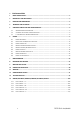
2 Bedienteile und Anschlüsse Bild 1 Endbegrenzung mit Gummipuffer Stator Schlitten Magnetisch codiertes Band Sensor (Wegmess-System) Befestigungsgewinde Linearachse am Stator (M6x12) Elektrische Schnittstelle Luftanschluss Befestigungsgewinde Nutzlast (M6x9), Zentriersenkung (Dm9H7x2,1) 3 FESTO ELGL-de 0904NH
3 Funktion und Anwendung Das elektrische Linearmodul Typ ELGL-… ist eine Handlingachse mit Luftlagerführung und integriertem Linearmotor. Die Antriebselemente und die Luftlagerung bilden eine Einheit, den Schlitten. Der Schlitten bewegt sich auf der Statorschiene. Ein separates Wegmesssystem liefert Signale an den Controller. Wegmesssystem, Controller und Motor arbeiten in einem geschlossenen Regelkreis.
Hinweis Auf der Linearmotorachse bzw. in der Verpackung kann sich ein Temperaturindikator zur Überwachung der Lager- und Transporttemperatur befinden. Bitte prüfen Sie unmittelbar nach Erhalt der Achse den Zustand des Temperaturindikators. Sollte sich der Temperaturindikator je nach Modell verfärbt haben, so wurde die Linearmotorachse bei Temperaturen unter 0°C gelagert oder transportiert. Dies kann zu Schäden an der Achse führen. Bitte wenden Sie sich in diesem Fall an den Festo Service.
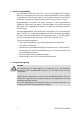
5 5.1 Voraussetzungen für den Produkteinsatz Anforderungen an das Personal Von der Linearachse können Gefahren ausgehen, wenn sie von nicht qualifiziertem und nicht ausgebildetem Personal, unsachgemäß oder nicht bestimmungsgemäß eingesetzt wird.
Warnung Bei Demontage der Bauteile der Linearachse können starke Magnetfelder auftreten! Starke Magnetfelder können bei Personen mit Implantaten (z. B. Herzschrittmacher), Hörgeräten und Schwangeren zu schweren gesundheitlichen Schäden oder zum Tode führen! • Lassen Sie den Linearmotor im Inneren der Linearachse stets eingebaut. Andernfalls können starke Magnetfelder auftreten. Im eingebauten Zustand sind die Magnetfelder unbedenklich.
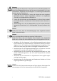
5.3 Luftaufbereitung und Drucküberwachung Vorsicht Um Sachschäden an der Linearachse zu vermeiden, muss die zugeführte Druckluft folgende Kriterien erfüllen: • Die Druckluft muss einen Nominaldruck entsprechend den technischen Daten aufweisen. • Die Druckluft muss frei von Wasser, Öl und Verunreinigungen sein. Die Druckluftaufbereitung muss deshalb mit einem Feinfilter (1 m) versehen sein und ggf. mit einem Kondensatabscheider.
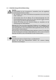
6 6.1 Einbau Einbau mechanisch Warnung Unkontrolliert bewegte Massen können zu Personenschäden (Quetschungen) oder zu Schäden an Gegenständen führen. • Prüfen Sie, ob zusätzlich Sicherungsmaßnahmen gegen Abgleiten der Nutzlast extern erforderlich sind. Die Linearachse hat keine Selbsthemmung. Eine Selbsthemmung liegt nur bei abgeschalteter Druckluft für die Luftlagerung vor.
Direktbefestigung Bild 3 Linearachse Grundfläche Zylinderschraube M6 (M4), max. Einschraubtiefe 12 mm (nicht Lieferumfang; max. Anzugsmoment M6=9Nm , M4=2,9Nm ) Fußbefestigung Bild 4 Linearachse Zylinderschraube M8 (nicht Lieferumfang; max.
Fußbefestigung, einstellbar Bild 5 Linearachse Zylinderschraube M8 (nicht Lieferumfang; max. Anzugsmoment M8=24Nm) Grundfläche Fuß-Justierbefestigung EAHF-L1-…-PJ Winkelfußbefestigung Bild 6 Linearachse Grundfläche Fußbefestigung EAHF-L1-… Zylinderschraube M6 (nicht Lieferumfang; max.
6.2 Befestigung von Objekten auf Schlitten Die Befestigung von Objekten auf dem Schlitten erfolgt direkt an der Oberseite des Schlittens oder über eine Adapterplatte. Dabei darf der Schlitten nicht verspannt oder verbogen werden. In der Regel werden Objekte auf dem Schlitten mit 4 Schrauben symmetrisch befestigt. Günstiger für eine verspannungsfreie Befestigung von Objekten ist jedoch eine 3-Punkt-Auflage, wenn dies konstruktiv möglich und sinnvoll ist.
6.3 Einbau der Nutzlast Berücksichtigen Sie die zulässigen Kräfte und Momente (siehe Kapitel Technische Daten). Die in der Grafik dargestellten Kräfte und Momente resultieren aus Ihrer Anwendung. Diese sind abhängig von folgenden Kräften: • Gewichtskräfte (Nutzlast/Eigenmasse) • Trägheitskräfte (Nutzlast/Eigenmasse) • Vorschubkraft • Gegenkräfte Bild 8 Die Kräfte und Momente auf die Luftlagerung ergeben sich je nach Dynamik (Bremsen/Beschleunigung).
6.4 Montage der Versorgungsleitungen Bild 9 Luftanschluss abgewinkelt (Optional z.B. QSL-M5-4) Luftanschluss gerade (Standard z.B. QSM-M5-4)) Befestigungsschrauben Steckverbinder (max. Anzugsmoment 1,2Nm) Die Anschlussleitungen lassen sich entsprechend den Einbauanforderungen anpassen.
Pneumatischer Anschluss: Der standardmäßig linksseitige Luftanschluss lässt sich auf die rechte Seite versetzen. Hierzu ist die rechtsseitige Verschlussschraube mit der linksseitigen Luftanschlussverschraubung aus zu tauschen. Optional stehen auch abgewinkelte Verschraubungen aus dem Festo-Katalog-Programm zu Verfügung. Elektrischer Anschluss: Der elektrische Steckverbinder lässt sich in 90 ° Schritten verdrehen.
Bild 10 Energiekettenhalter links Typ EAHT-L1-E6-… Energiekettenhalter rechts Typ EAHT-L1-E6-… (max.
6.5 Montage der End-/Referenzschalter Bild 11 Fußbefestigung EAHF-… Sensorhalter EAPR-… Befestigungsschrauben (max. Anzugsmomente M3= 1,2Nm) Für die Montage von End- und Referenzschaltern steht ein Sensorhalter Bausatz vom Typ EAPR zur Verfügung. Mit dem beigefügten Montagematerial lässt sich der Sensorhalter auf die verschiedenen Fußbefestigungen der ELGL Antriebe montieren.
6.6 Einbau elektrisch Warnung Die zulässige Betriebstemperatur der Linearachse beträgt 70 °C. Bei höheren Betriebstemperaturen besteht Verbrennungsgefahr und der Motor kann zerstört werden! Schließen Sie in jedem Fall den Temperatursensor an, um Personenschäden oder Schäden an der Linearachse zu vermeiden! Warnung Durch direkte ESD Entladungen auf die Pins des Messsystems (bei geöffnetem Steckverbinder), kann dieses beschädigt werden.
Bild 12 Motorleitung NEBM-T1G7-E-…-N-LE7 Anschluss Motorleitung (Block schwarz) Anschluss Motorleitung (Block blau) Anschluss Sensorleitung (Block rot) Anschluss Sensorleitung (Block gelb) Encoderleitung NEBM-T1G8-E-…-N-S1G15 Anschlussbelegung Sensorleitung BISS-Schnittstelle (Block rot) Benennung Adernfarbe Steckverbinder Datenausgang + (BISS/RS485) SLO+ Grün Rot Pin 1 Datenausgang (BISS/RS485) SLO- Gelb Rot Pin 2 Messsystem GND GND Schwarz Rot Pin 3 Messsystem VCC (+5VDC±10%) VCC Braun
Anschlussbelegung Sensorleitung (Block gelb) Benennung Adernfarbe Steckverbinder Messsystem GND Sens GND Sens NC Gelb Pin 1 Messsystem VCC Sens VCC Sens NC Gelb Pin 2 Referenzschalter 1+ Ref 1+ NC Gelb Pin 3 Referenzschalter 1- Ref 1- NC Gelb Pin 4 Referenzschalter 2+ Ref 2+ NC Gelb Pin 5 Referenzschalter 2- Ref 2- NC Gelb Pin 6 Anschlussbelegung Motorleitung (Block blau) Benennung Adernfarbe Steckverbinder Temperaturfühler + MT dig+ Weiß Blau Pin 1 Temperaturfühler - MT d
6.7 Messsystem BiSS-Schnittstelle Das BiSS-Interface ist eine 2-Leiter-Schnittstelle zur störsicheren Sensoranbindung. Im Unterschied zur SSI-Schnittstelle ist die Datenübertragung bidirektional, d.h. es können auch Daten z.B. zur Parametrierung in den Sensor geschrieben werden. Der Datenverkehr erfolgt über eine vom Master getriebene Takt-Leitung und eine vom Sensor bediente Datenleitung als serielle Übertragung.
6.8 Einbau pneumatisch Der Aufbau der Luftlager des Motorläufers und die Gesamtkonstruktion erlaubt die Verwendung der Luftlager auch als Feststelleinheit für sicherheitsgerichtete Funktionen des Antriebssystems. Bild 14 Linearantrieb ELGL Wartungseinheit / Druckluftaufbereitung Schnellschaltventil / Ventil Hierzu wird die Druckluft zum Läufer z.B. über ein Schnellschaltventil geführt und das Ventil selbst an den Bremsausgang des Motorcontrollers z.B. CMMP gelegt.
Die Delayzeiten für ein Öffnen der Feststelleinheit bei Belüftung ist zum großen Teil von den Kapazitäten im Druckluftnetz abhängig und liegt bei ca. 100ms wenn keine Druckspeicher und kurze Leitungen verwendet werden. Warnung Die Feststellfunktion des Luftlagers über die Abschaltung der Druckluftzufuhr ist ausschließlich als Feststellfunktion verwendbar. Eine Verwendung als Betriebsbremse führt zu einer Beschädigung der Lagerflächen und damit zur Zerstörung des Motorsystems.
7 Inbetriebnahme Warnung Stellen Sie sicher, dass im Bewegungsbereich der Linearachse • niemand in die Laufrichtung der bewegten Bauteile greift (z. B. durch Schutzgitter), • sich keine Fremdgegenstände befinden. Erst bei völligem Stillstand aller bewegten Teile und Abschalten der Versorgungsspannung darf ein Greifen an die Linearachse möglich sein. Warnung Vollziehen Sie die Erstinbetriebnahme des Antriebssystems mit einer Referenzfahrt und geringen Geschwindigkeiten, Massen und Kräften.
Gehen Sie wie folgt vor: 1. Starten Sie einen Probelauf. 2. Prüfen Sie, ob die Einstellungen am ELGL-... /Contoller verändert werden müssen. Abweichende Positioniergenauigkeit oder Überschwingen des Systems hat möglicherweise folgende Ursachen: - zu hohe Zusatzmasse - zu hohe Dynamik - zu Schwingungen neigender mechanischer Aufbau - fehlerhafte Parametrierung am Controller - zu hoher Verschiebewiderstand (Verspannungen beim Einbau/Anbau-teile). 3. Wiederholen Sie ggf. den Probelauf.
9 Wartung und Pflege Vorsicht Das Verwenden von Aceton oder ähnlichen kunststofflösenden Reinigungsmitteln kann die Linearachse zerstören! Verwenden Sie zur Reinigung alkoholhaltige Reiniger.
• • • • • Alle Schutzeinrichtungen sind sofort nach Beendigung der Wartungs- und Reparaturarbeiten wieder ordnungsgemäß zu installieren und ihre Funktion ist zu prüfen! Schließen Sie niemals Komponenten ohne ordnungsgemäß installierte Gehäuse oder Schutzabdeckungen an das Stromnetz an. Die elektrischen Ausrüstungen sind regelmäßig von einer Elektrofachkraft zu prüfen. Alle Mängel, wie lose Verbindungen, defekte oder beschädigte Kabel, sind sofort zu beseitigen.
10 Ausbau und Reparatur Gefahr Bei Demontage der Bauteile der Linearachse können starke Magnetfelder auftreten! Starke Magnetfelder können bei Personen mit Implantaten (z. B. Herzschrittmacher), Hörgeräten und Schwangeren zu schweren gesundheitlichen Schäden oder zum Tode führen! • Eine Demontage der Bauteile der Linearachse ist grundsätzlich nicht gestattet. • Lassen Sie den Linearmotor im Inneren der Linearachse stets eingebaut. Andernfalls können starke Magnetfelder auftreten.
11 Zubehör Bild 15 29 FESTO ELGL-de 0904NH
Bezeichnung Typ ELGL-LAS 30 Linearachse, Grundausführung ELGL-LAS-… Wartungs- und Reparaturset 64 120 X X Stoßdämpfer YSRW-… 7 – 10 Zentrierhülse ZBH-9 X Näherungsschalter SIEN-M8B-… X Steckdosenleitung NEBU-M8W3… X Steckdosenleitung NEBU-M8G3… X Näherungsschalter SIES-Q8B-PO-… X Sensorhalter EAPR-L1-S X Fußbefestigung EAHF-L1-…-P X Anbausatz EAHC-L1-… X Linearantrieb DGC-18-… X Fuß-Justierbefestigung EAHF-L1-…-PJ X Fußbefestigung EAHF-L1-… X Anbausatz EAHT-L1-E
12 Störungsbeseitigung Warnung Lebensgefährliche Spannung ! Arbeiten bei unter Spannung stehender Anlage dürfen nur von erfahrenen Elektrofachkräften ausgeführt werden und sind nur zur Fehlerdiagnose erlaubt! Für die Fehlersuche bei unter Spannung stehender Anlage sind ortsveränderliche Schutzeinrichtungen (z. B. ein Schutz-Trenntransformator) zur Verfügung zu stellen. Je nach Art der Arbeit und den Umgebungsverhältnissen können weitere Maßnahmen und Hilfsmittel – wie z. B.
Störung Mögliche Ursache Abhilfe Fehlerhafte Parametrierung Parameter im Controller prüfen Linearachse befindet sich hinter Linearachse manuell aus Endlage der Endlage / Referenzfahrtfehler herausschieben (Luft ein, Strom aus!) Freigabe fehlt Störung bei punktfindung 24 V auf Freigabeeingang anlegen Kommutierungs- Ungünstiger Resonanzfall für das Kommutierungswinkelgewählte Kommutierungswinkel- Suchverfahren im FCT wechseln verfahren bzw. Parametrierung ändern.
13 Technische Daten ELGL30-…-S ELGL64-…-S ELGL64-…-M ELGL120-…-S ELGL120-…-M ELGL120-…-L Konstruktive Eigenschaften Konstruktiver Aufbau Elektrischer Linearantrieb nach dem Hybrid-Switched-Reluctance Prinzip (H-SRM) Einbaulage Vorzugsweise waagrecht, Vertikalbetrieb auf Anfrage zulässig (Zusatzinformationen beachten, Nutzung Halterungen, …) Endlagenschutz Integrierte Puffer für geringe Dämpfungsenergien (minimaler Schutz) Messprinzip Wegmesssystem Magnetisch inkrementell Temperaturüberwachung
ELGL30-…-S Anforderungen an die Luftqualität ELGL64-…-S ELGL64-…-M ELGL120-…-S ELGL120-…-M ELGL120-…-L Mindestanforderungen an die Luftqualität: Luftqualität nach ISO 8573-1: für Staub Klasse 2 (max.Teilchengröße 1µm; max. Teilchendichte 1 mg/m3) für Wasser Klasse 4 (<=+3 °C Drucktaupunkt) für Öl Klasse 2 (<=0,1 mg/m3 ölfrei) Empfohlene Luftqualität: Luftqualität nach ISO 8573-1: für Staub Klasse 1 (max.Teilchengröße 0,1µm; max.
Bild 16 ELGL30-…-S ELGL64-…-S ELGL64-…-M ELGL120-…-S ELGL120-…-M ELGL120-…-L Mechanische Eigenschaften bei statischer Belastung Traglast F z N 160 700 1.000 1.300 1.700 2.
1 Table of contents 1 TABLE OF CONTENTS ........................................................................................................................... 36 2 CONTROL ELEMENTS AND CONNECTIONS .......................................................................................... 37 3 FUNCTION AND APPLICATION .............................................................................................................. 38 4 TRANSPORT AND STORAGE ..........................................
2 Control elements and connections Fig. 17 End position limiter with rubber buffer Stator Slide Magnetically coded tape Sensor (displacement encoder) Mounting thread for linear axis on the stator (M6x12) Electrical interface Air connection Mounting thread for effective load (M6x9), centring countersink (Dm9H7x2.
3 Function and application The electric linear module type ELGL-... is a handling axis with air-cushion bearing guide and integrated linear motor. The driving components and the air cushion bearing form one unit, the slide. The slide moves on the stator rail. A separate displacement encoder supplies signals to the controller. The displacement encoder, controller and motor operate in a closed-loop control circuit.
Note A temperature indicator for monitoring the storage and transport temperatures can be found on the linear motor axis or in the packaging. Please check the status of the temperature indicator immediately upon receiving the axis. Should the temperature indicator have changed colour depending on the model in question, then the linear motor axis has been stored or transported at temperatures below 0°C. This can lead to damage to the axis. In this case, please consult the Festo service department.
5 5.1 Requirements for product use Requirements to be met by personnel The linear axis can prove hazardous if it used by unqualified and untrained personnel, or if it is used improperly or is not used as intended.
Warning Strong magnetic fields may occur when components of the linear axis are being dismantled. Strong magnetic fields can lead to serious health risks or even death for persons with implants (e.g. heart pacemakers) or hearing aids, and pregnant women. • Always leave the linear motor fitted inside the linear axis. Otherwise strong magnetic fields may occur. When the device is fitted inside, the magnetic fields are harmless.
5.3 Air conditioning and pressure monitoring Caution To prevent material damage to the linear axis, the supplied compressed air must fulfil the following criteria: • The compressed air must have a rated pressure corresponding to the technical data. • The compressed air has to be free of water, oil and contamination. The compressed air preparation must therefore be equipped with a fine filter (1 m) and, if necessary, with a condensate separator.
6 6.1 Installation Mechanical installation Warning Uncontrolled moving masses can cause injury to people (squashing) or damage to property. • Check whether additional external safety measures are required to prevent the effective load from sliding down. The linear axis has no automatic locking. Automatic locking is only available when the compressed air for the air cushion bearing is turned off.
Direct mounting Fig. 19 Linear axis Base Socket head screw M6 (M4), max. screw-in depth 12 mm (not in scope of delivery; max. tightening torque M6=9 Nm , M4=2.9 Nm ) Foot mounting Fig. 20 Linear axis Socket head screw M8 (not in scope of delivery; max.
Foot mounting, adjustable Fig. 21 Linear axis Socket head screw M8 (not in scope of delivery; max. tightening torque M8=24 Nm) Base Adjustable foot mounting EAHF-L1-…-PJ Angled foot mounting Fig. 22 Linear axis Base Foot mounting EAHF-L1-… Socket head screw M6 (not in scope of delivery; max.
6.2 Mounting of objects on the slide Objects are mounted directly on the top of the slide or via an adapter plate. The slide must not be distorted or bent. Objects are normally fastened symmetrically on the slide using 4 screws. However, a 3-point support is more favourable for fastening the objects without distortion if the design allows it and it is practical. For easier handling, the slides are equipped with screw terminals. These are uniformly surface-ground to provide an even and punctiform support.
6.3 Installing the effective load Take into account the permitted forces and torques (see chapter "Technical data"). The forces and torques represented in the graph result from your application. These are dependent on the following forces: • Forces due to weight (effective load/mass) • Inertial forces (effective load/mass) • Feed force • Counteracting forces Fig. 24 The resulting forces and torques on the air cushion bearing depend on the dynamics (braking/acceleration).
6.4 Connecting the power supply cables Fig. 25 Angled air connection (optional, e.g. QSL-M5-4) Straight air connection (standard, e.g. QSM-M5-4) Mounting screws for plug connector (max. tightening torque 1.2 Nm) The connecting cables can be adapted according to the mounting requirements.
Pneumatic connection: The standard left-hand air connection can be moved to the right-hand side. To do this, the right-hand plug screw must be replaced with the left-hand threaded air fitting. As an option, angled screw fittings from the Festo catalogue range are also available. Electrical connection: The electrical plug connector can be turned in 90° steps. To do this, the four retaining screws must be removed when the plug connector is opened and the plug connector turned carefully.
Fig. 26 Left cable chain holder, type EAHT-L1-E6-… Right cable chain holder, type EAHT-L1-E6-… (max. tightening torques M5=5.
6.5 Mounting the limit/reference switches Fig. 27 Foot mounting EAHF-… Sensor retainer EAPR-… Mounting screws (max. tightening torque M3= 1.2 Nm) An EAPR sensor retainer kit is available for mounting the limit and reference switches. Using the included mounting material, the sensor retainer can be mounted on the various foot mountings for the ELGL drives.
6.6 Electrical installation Warning The maximum operating temperature of the linear axis is 70 °C. If the operating temperature is higher than this, there is a danger of burning and the motor could be destroyed. Always connect up the temperature sensor to avoid injuries to people or damage to the linear axis. Warning The displacement encoder can be damaged by direct electro-static discharges onto its pins (if the plug connector is open).
Fig.
Pin allocation for sensor cable (yellow block) Designation Wire colour Plug connector Displacement encoder GND Sens GND Sens NC Yellow pin 1 Displacement encoder VCC Sens VCC Sens NC Yellow pin 2 Reference switch 1+ Ref 1+ NC Yellow pin 3 Reference switch 1- Ref 1- NC Yellow pin 4 Reference switch 2+ Ref 2+ NC Yellow pin 5 Reference switch 2- Ref 2- NC Yellow pin 6 Pin allocation for motor cable (blue block) Designation Wire colour Plug connector Temperature sensor + MT dig+
6.7 Displacement encoder for BiSS interface The BiSS interface is a 2-wire interface for interference-immune sensor connection. In contrast to the SSI interface, the data transmission is bi-directional, which means, for example, that data can also be written into the sensor for parametrisation. Data is transmitted via a pulse cable controlled by the master and a data cable controlled by the sensor as serial transmission.
6.8 Installing the pneumatic system The arrangement of the rotor's air cushion bearing and the overall design also allows the use of the aerostatic bearing as a clamping unit for safety oriented functions of the drive system. Fig. 30 Linear drive ELGL Service unit / Compressed air preparation Fast-switching valve / Valve The compressed air to the slide is guided, for example, via a fast switching valve and the valve itself is placed on the brake output of the motor controller, e.g. CMMP.
The delay times for opening the clamping unit with pressurisation is largely dependent on the capacities in the compressed air system and is approx. 100 ms if no air reservoirs and short cables are used. Warning The clamping function of the air cushion bearing through switching off the air supply can only be used as a clamping function. Using it as a service brake leads to the bearing surfaces being damaged and thus to the destruction of the motor system.
7 Commissioning Warning Ensure the following in the movement area around the linear axis • nobody can place his/her hand in the path of the moving parts (e.g. by providing a protective crate) • there are no objects obstructing the positioning path. It should not be possible to touch the linear axis until all moving parts have come to a complete standstill and the power supply has been switched off.
Proceed as follows: 1. Start a test run. 2. Check whether the settings on the ELGL-... /controller have to be changed. Deviations in positioning accuracy or overswing of the system could be caused by the following: - additional mass too high - dynamics too high - mechanical structure tends to vibrate - incorrect parametrisation on the controller - resistance to shifting too high (stress with fitting/plug-in parts). 3. If necessary, repeat the test run.
9 Service and maintenance Caution The use of acetone or similar synthetic-material dissolving cleaning agents can destroy the linear axis. For cleaning, use cleaning agents containing alcohol. Caution Lifting up and putting down the slide on the stator can dirty and/or damage the surfaces of the air cushion bearing. Avoid any unnecessary lifting up and putting down of the slide on the stator. Caution Moving the slide with force on the stator can damage the surfaces of the air cushion bearing.
• • • • • • • • All protective devices must be properly reinstalled immediately after the maintenance and repair work has finished, and their correct functioning must be checked. Never connect up components to the power supply without properly installed housings or safety covers. The electrical equipment must be regularly checked by an expert electrical technician. All defects such as loose connections, faulty or damaged cables must be rectified immediately.
10 Disassembly and repairs Danger Strong magnetic fields may occur when components of the linear axis are being dismantled. Strong magnetic fields can lead to serious health risks or even death for persons with implants (e.g. heart pacemakers) or hearing aids, and pregnant women. • Dismantling the components of the linear axis is never permitted. • Always leave the linear motor fitted inside the linear axis. Otherwise strong magnetic fields may occur.
11 Accessories Fig.
Designation Type ELGL-LAS 30 Linear axis, basic design ELGL-LAS-… Maintenance and repair kit 64 120 X X Shock absorber YSRW-… 7 – 10 Centring sleeve ZBH-9 X Proximity sensor SIEN-M8B-… X Plug socket with cable NEBU-M8W3… X Plug socket with cable NEBU-M8G3… X Proximity sensor SIES-Q8B-PO-… X Sensor retainer EAPR-L1-S X Foot mounting EAHF-L1-…-P X Mounting kit EAHC-L1-… X Linear drive DGC-18-… X Foot mounting, adjustable EAHF-L1-…-PJ X Foot mounting EAHF-L1-… X Mou
12 Troubleshooting Warning Dangerous voltage Work on a live system may only be carried out by experienced, expert electrical technicians and is only permitted for the purpose of error diagnosis. For fault-finding in a live system, mobile protective equipment (e.g. a protective isolating transformer) has to be made available.
Fault Possible cause Remedy Linear axis not responding Temperature monitoring active Observe permitted loading values (take into account temperature fluctuations during course of year) Incorrect parametrisation Check parameters in the controller Linear axis is behind the end Manually push the linear axis out position / homing fault of the end position (air on, power off!) Not enabled Apply 24 V to enable input Malfunction in the commutation Unfavourable resonance for the Change commutation angle p
13 Technical data ELGL30-…-S ELGL64-…-S ELGL64-…-M ELGL120-…-S ELGL120-…-M ELGL120-…-L Design properties Constructional design Electric linear drive in accordance with the hybrid-switchedreluctance principle (H-SRM) Mounting position Preferably horizontal, vertical operation permissible on request (observe additional information, use of supports, …) End position protection Integrated buffer for slight cushioning energy (minimal protection) Measuring principle of displacement encoder Magnetic in
ELGL30-…-S Requirements on the air quality ELGL64-…-S ELGL64-…-M ELGL120-…-S ELGL120-…-M ELGL120-…-L Minimum requirements on the air quality: Air quality to ISO 8573-1: For dust Class 2 (max. particle size 1µm; max. particle density 1 mg/m3) For water Class 4 (<=+3 °C pressure dew point) For oil Class 2 (<=0.1 mg/m3 oil-free) Recommended air quality: Air quality to ISO 8573-1: For dust Class 1 (max.particle size 0.1µm; max. particle density 0.
Fig. 32 ELGL30-…-S ELGL64-…-S ELGL64-…-M ELGL120-…-S ELGL120-…-M ELGL120-…-L Mechanical properties during static load Load F z N 160 700 1,000 1,300 1,700 2,500 N 35 140 220 260 300 400 Fy N 600 600 600 600 600 600 Mx Nm 1.
1 Índice 1 ÍNDICE .................................................................................................................................................. 70 2 ELEMENTOS DE MANDO Y CONEXIONES ............................................................................................. 71 3 FUNCIONAMIENTO Y APLICACIÓN ....................................................................................................... 72 4 TRANSPORTE Y ALMACENAMIENTO .....................................
2 Elementos de mando y conexiones Fig.
3 Funcionamiento y aplicación El módulo lineal eléctrico del tipo ELGL-… es un eje de manipulación con una guía sobre colchón de aire y un motor lineal integrado. Los elementos motrices y el colchón de aire forman una unidad: el carro. El carro se desplaza sobre el riel del estator. Un sistema de medición de recorrido aparte envía señales al controlador. El sistema de medición de recorrido, el controlador y el motor son controlados por medio de un circuito de regulación en bucle cerrado.
Indicación En el motor lineal o en el embalaje puede haber un indicador de temperatura para controlar la temperatura de almacenamiento y de transporte. Compruebe inmediatamente el estado del indicador de temperatura cuando reciba el eje. Si el indicador de temperatura está en color (según el modelo), el eje del motor lineal ha sido almacenado o transportado a temperaturas inferiores a 0 °C. Esto puede dañar el eje. Póngase en contacto con el servicio técnico de Festo.
5 5.1 Requerimientos para la utilización del producto Requerimientos que debe cumplir el personal El eje lineal puede provocar accidentes peligrosos si es manejado por personal no cualificado ni formado, si se utiliza incorrectamente o de manera no conforme a lo previsto.
Advertencia Al desmontar los componentes del eje lineal pueden generarse campos magnéticos fuertes. Los campos magnéticos fuertes pueden provocar lesiones graves o incluso la muerte a personas con determinadas prótesis (p. ej. marcapasos), instrumentos de audición y a mujeres embarazadas. • No desmonte nunca el motor lineal del interior del eje lineal. De lo contrario pueden generarse campos magnéticos fuertes. En estado montado, los campos magnéticos son inofensivos.
5.3 Acondicionamiento del aire y control de la presión Atención Para impedir que se produzcan daños en el eje lineal, el aire comprimido alimentado debe cumplir los criterios siguientes: • La presión nominal del aire comprimido debe cumplir lo establecido en las especificaciones técnicas. • No debe haber agua, aceite ni suciedad en el aire comprimido. Para ello, el acondicionamiento del aire comprimido debe disponer de un filtro micrónico (1 m) y, si es necesario, de un separador de la condensación.
6 6.1 Montaje Instalación mecánica Advertencia Las masas descontroladas pueden causar lesiones a las personas (aplastamiento) o daños a los objetos. • Compruebe si es necesario tomar medidas de seguridad adicionales externas contra el deslizamiento de la carga útil. El eje lineal no dispone de autobloqueo. El autobloqueo sólo existe cuando el aire comprimido para el colchón de aire está desconectado.
Montaje directo Fig. 35 Eje lineal Base inferior Tornillo cilíndrico M6 (M4), máx. profundidad de atornillado 12 mm (no incluido en el suministro; máx. par de apriete M6 = 9 Nm, M4 = 2,9 Nm) Fijación por pies Fig. 36 Eje lineal Tornillo cilíndrico M8 (no incluido en el suministro; máx.
Fijación por pies, regulable Fig. 37 Eje lineal Tornillo cilíndrico M8 (no incluido en el suministro; máx. par de apriete M8 = 24 Nm) Base inferior Fijación ajustable por pies EAHF-L1-…-PJ Fijación por pies en ángulo Fig. 38 Eje lineal Base inferior Fijación por pies EAHF-L1-... Tornillo cilíndrico M6 (no incluido en el suministro; máx.
6.2 Fijación de objetos en el carro Los objetos se fijan en el carro directamente sobre la parte superior o sobre una placa adaptadora. El carro no debe deformarse por tensiones ni doblarse. Por lo general, en el carro se fijan objetos simétricamente con cuatro tornillos. Una opción más idónea para fijar objetos sin deformar por tensiones es el apoyo de tres puntos, si la construcción así lo permite y es adecuado. Los carros disponen de terminales de atornillado para facilitar la manipulación.
6.3 Fijación de la carga útil Observe las fuerzas y pares permitidos (véase el capítulo Especificaciones técnicas). Las fuerzas y pares que se muestran en la gráfica se derivan de cómo use el eje. Éstas dependen de las fuerzas siguientes: • Fuerzas debidas al peso (carga útil/peso propio). • Fuerzas de inercia (carga útil/peso propio). • Fuerza de avance. • Fuerzas antagónicas. Fig. 40 Las fuerzas y los pares aplicados al colchón de aire se obtienen en función de la dinámica (frenado/aceleración).
6.4 Montaje de las conexiones de alimentación Fig. 41 Conexión de aire acodada (opcional, p. ej., QSL-M5-4) Conexión de aire recta (estándar, p. ej., QSM-M5-4) Tornillos de fijación del conector enchufable (par máx. de apriete 1,2 Nm) Los cables de conexión pueden adaptarse conforme a los requerimientos de montaje.
Conexión neumática: La conexión de aire estándar del lado izquierdo puede pasarse al lado derecho. Para ello puede cambiarse el tornillo de cierre del lado derecho por el racor para conexión de aire del lado izquierdo. Opcionalmente también pueden utilizarse racores acodados del catálogo de Festo. Conexión eléctrica: El conector eléctrico enchufable puede girarse en ángulos de 90°.
Fig. 42 Soporte izquierdo de la cadena de arrastre, tipo EAHT-L1-E6-… Soporte derecho de la cadena de arrastre, tipo EAHT-L1-E6-… (pares máx.
6.5 Montaje de los detectores de final de carrera y de los interruptores de referencia Fig. 43 Fijación por pies EAHF-... Soporte para detector EAPR-... Tornillos de fijación (pares máx. de apriete M3 = 1,2 Nm) Para montar los detectores de final de carrera y los interruptores de referencia existe un conjunto de soportes para detectores del tipo EAPR. Con el material de montaje suministrado puede montarse el soporte para detector sobre las diferentes fijaciones por pies de los actuadores ELGL.
6.6 Instalación eléctrica Advertencia La temperatura de funcionamiento permitida del eje lineal es de 70 °C. A temperaturas de funcionamiento superiores se corre el riesgo de quemaduras y el motor puede destruirse por efecto del calor. Conecte siempre el sensor de temperatura para impedir lesiones personales o daños en el eje lineal. Advertencia Las descargas electrostáticas directas (ESD) en los pines del sistema de medición del recorrido (con el conector enchufable abierto) pueden dañar dicho sistema.
Fig.
Ocupación de conexiones del cable de sensor (bloque amarillo) Denominación Color de los hilos Conectores enchufables Sistema de medición del recorrido GND Sens GND Sens NC Pin amarillo 1 Sistema de medición del recorrido VCC Sens VCC Sens NC Pin amarillo 2 Interruptor de referencia 1+ Ref 1+ NC Pin amarillo 3 Interruptor de referencia 1- Ref 1- NC Pin amarillo 4 Interruptor de referencia 2+ Ref 2+ NC Pin amarillo 5 Interruptor de referencia 2- Ref 2- NC Pin amarillo 6 Ocupación de
6.7 Interface BISS del sistema de medición del recorrido La interface BISS es una interface de dos conductores para conectar sensores a prueba de interferencias. A diferencia de la interface SSI, la transmisión de datos es bidireccional, es decir, también es posible escribir datos en el sensor, p. ej., para parametrizar. El tráfico de datos se efectúa a través de un cable de impulsos desde el máster y a través de una línea de datos controlada por el sensor como transmisión en serie.
6.8 Instalación neumática La estructura del colchón de aire del inducido del motor y la construcción entera permiten utilizar el colchón de aire también como unidad de bloqueo para funciones de seguridad del sistema de accionamiento. Fig. 46 Actuador lineal ELGL Unidad de mantenimiento / acondicionamiento del aire comprimido Válvula de respuesta rápida / válvula Para ello, el aire comprimido se conduce a la unidad lineal, p. ej.
Con la función de freno automática también es posible dejar el actuador sin corriente y en estado de bloqueo un determinado tiempo, lo que permite ahorrar energía eléctrica. Los tiempos de retardo para abrir la unidad de bloqueo durante la alimentación dependen en gran medida de la capacidad de la red del aire comprimido y son de 100 ms aproximadamente si no se emplean acumuladores de aire comprimido y se utilizan tubos cortos.
7 Puesta en funcionamiento Advertencia Asegúrese de lo siguiente respecto a la zona de movimientos alrededor del eje lineal: • Que nadie pueda poner la mano dentro del recorrido de los componentes en movimiento (p. ej. colocando una rejilla protectora). • Que no haya objetos extraños. Debe ser imposible acceder al eje lineal hasta que todas las piezas móviles estén paradas y la tensión de alimentación desconectada.
Proceda del modo siguiente: 1. Inicie un funcionamiento de prueba. 2. Compruebe si deben cambiarse los ajustes en el controlador del ELGL-... Las oscilaciones o las imprecisiones de posicionado del sistema pueden tener las siguientes causas: - Masa adicional demasiado alta. - Dinámica demasiado elevada. - La estructura mecánica tiende a vibrar. - Parametrización incorrecta en el controlador.
9 Cuidados y mantenimiento Atención La utilización de acetona u otros detergentes disolventes de materiales sintéticos puede destruir el eje lineal. Para limpiar, utilice productos de limpieza con alcohol. Atención Al levantar y depositar el carro sobre el estator pueden ensuciarse y/o dañarse las superficies del colchón de aire. No levante ni deposite el carro sobre el estator innecesariamente.
• • • • • • • • Tras finalizar los trabajos de mantenimiento y de reparación, los dispositivos de protección deben volver a instalarse inmediatamente y debe comprobarse su funcionamiento. No conecte nunca componentes a la red eléctrica sin que sus cubiertas o tapas no estén instaladas correctamente. El equipamiento eléctrico debe ser revisado regularmente por un electricista. Todos los defectos, como conexiones sueltas o cables defectuosos o dañados, deben corregirse inmediatamente.
10 Desmontaje y reparaciones Peligro Al desmontar los componentes del eje lineal pueden generarse campos magnéticos fuertes. Los campos magnéticos fuertes pueden provocar lesiones graves o incluso la muerte a personas con determinadas prótesis (p. ej. marcapasos), instrumentos de audición y a mujeres embarazadas. • En general, está prohibido desmontar los componentes del eje lineal. • No desmonte nunca el motor lineal del interior del eje lineal. De lo contrario pueden generarse campos magnéticos fuertes.
11 Accesorios Fig.
Designación Tipo ELGL-LAS 30 Eje lineal, versión básica ELGL-LAS-… Juego de mantenimiento y reparación 120 X X Amortiguador YSRW-… 7 – 10 Casquillo para centrar ZBH-9 X Detector de proximidad SIEN-M8B-… X Cable de conexión con conector NEBU-M8W3… X Cable de conexión con conector NEBU-M8G3… X Detector de proximidad SIES-Q8B-PO-… X Soporte para detector EAPR-L1-S X Fijación por pies EAHF-L1-…-P X Fijación EAHC-L1-… X Actuador lineal DGC-18-… X Fijación ajustable por pies
12 Eliminación de fallos Advertencia Tensión peligrosa que puede causar la muerte. El trabajo en instalaciones con tensión sólo debe ser efectuado por electricistas experimentados con el único objeto de diagnosticar errores. Para localizar errores en instalaciones con tensión debe haber dispositivos de protección móviles (p. ej., un transformador de aislamiento de protección).
Fallo Posible causa Remedio Parametrización incorrecta Comprobar los parámetros del controlador El eje lineal se encuentra detrás Retirar a mano el eje lineal de la de la posición final / error en el posición final (aire conectado, recorrido de referencia corriente desconectada).
13 Especificaciones técnicas ELGL30-…-S ELGL64-…-S ELGL64-…-M ELGL120-…-S ELGL120-…-M ELGL120-…-L Características de construcción Forma constructiva Actuador lineal eléctrico conforme al principio de Hybrid-SwitchedReluctance (H-SRM; actuador de reluctancia autoconmutado híbrido) Posición de montaje Preferentemente horizontal; funcionamiento en vertical permitido tras consulta (observar la información adicional, uso de sujeciones, etc.
ELGL30-…-S Requisitos de la calidad del aire ELGL64-…-S ELGL64-…-M ELGL120-…-S ELGL120-…-M ELGL120-…-L Requisitos mínimos de la calidad del aire: Calidad del aire según ISO 8573-1: Para polvo Clase 2 (tamaño máx. de las partículas 1 µm; densidad máx. de las partículas 1 mg/m3) Para agua Clase 4 (<=+3 °C punto de condensación bajo presión) Para aceite Clase 2 (<=0,1 mg/m3 sin aceite) Calidad del aire recomendada: Calidad del aire según ISO 8573-1: Para polvo Clase 1 (tamaño máx.
Fig. 48 ELGL30-…-S ELGL64-…-S ELGL64-…-M ELGL120-…-S ELGL120-…-M ELGL120-…-L Características mecánicas con carga estática Carga F z N 160 700 1.000 1.300 1.700 2.
1 Sommaire 1 SOMMAIRE ......................................................................................................................................... 104 2 ELÉMENTS DE COMMANDE ET RACCORDEMENTS ............................................................................ 105 3 FONCTIONNEMENT/APPLICATION..................................................................................................... 106 4 TRANSPORT ET STOCKAGE ............................................................
2 Eléments de commande et raccordements Figure 49 Limitation fin de course avec tampon en caoutchouc Stator Chariot Règle magnétique à codage Capteur (système de mesure de déplacement) Taraudage de fixation sur axe linéaire au niveau du stator (M6x12) Interface électrique Prise d'air Taraudage de fixation pour la charge utile (M6x9), lamage central (Dm9H7x2,1) 105 FESTO ELGL-fr 0904NH
3 Fonctionnement/application Le module linéaire électrique de type EGL-... est un axe de manipulation avec guidage sur coussin d'air et moteur linéaire intégré. Les éléments d'entraînement et le guidage sur coussin d'air forment une unité, le chariot. Celui-ci se déplace sur la glissière du stator. Un système de mesure de déplacement séparé envoie des signaux au contrôleur. Le système de mesure de déplacement, le contrôleur et le moteur fonctionnent en boucle de régulation fermée.
Nota Sur l'axe de moteur linéaire ou dans l'emballage peut se trouver un indicateur de température contrôlant la température de stockage et de transport. Prière de vérifier immédiatement après la réception de l'axe l'état de l'indicateur de température. Si, selon le modèle, l'indicateur de température s'est décoloré, alors l'axe du moteur linéaire a été stocké à des températures inférieures à 0 °C. L'axe risque d'être endommagé. Prière de vous adresser dans ce cas au service Festo.
5 5.1 Conditions d'utilisation Exigences imposées au personnel L'axe linéaire peut constituer un danger lorsque du personnel non qualifié et inexpérimenté l'utilise de manière inappropriée ou non conforme au règlement. Sont qualifiées au sens des présentes notices d'utilisation toutes les personnes familiarisées avec le montage, la mise en service, l'exploitation, la maintenance des axes linéaires électriques stockés à l'air libre.
Avertissement De forts champs magnétiques peuvent apparaître lors du démontage des composants ! Chez les personnes avec des implants (p. ex. stimulateur cardiaque), des appareils auditifs ou chez les femmes enceintes, les champs magnétiques peuvent provoquer de graves dommages corporels voire entraîner la mort ! • Ne jamais démonter le moteur linéaire à l'intérieur de l'axe. Sinon des champs magnétiques puissants peuvent apparaître. A l'état monté, les champs magnétiques ne présentent aucun risque.
5.3 Conditionnement de l'air et surveillance de la pression Attention Afin d'éviter des dommages matériels au niveau de l'axe linéaire, l'alimentation en air comprimé doit remplir les critères suivants : • L'air comprimé doit atteindre une pression nominale correspondant aux caractéristiques techniques. • L'air comprimé doit être exempt d'eau, d'huile ou d'impuretés. Le conditionnement de l'air comprimé doit être pour cela pourvu d'un filtre fin (1 m) et, le cas échéant, d'un purgeur de condensats.
6 6.1 Montage Montage mécanique Avertissement Des mouvements de masses incontrôlés peuvent blesser des personnes (contusions) ou endommager des objets. • Vérifier si des mesures de sécurité supplémentaires externes sont nécessaires pour éviter un glissement de la charge utile. L'axe linéaire ne dispose pas d'un verrouillage automatique. Un tel verrouillage n'est présent que lorsque l'alimentation en air comprimé est arrêtée pendant l'utilisation des coussins d'air.
Fixation directe Figure 51 Axe linéaire Semelle Vis à tête cylindrique M6 (M4), profondeur de vis max. 12 mm (non comprise dans la livraison; couple de serrage max. M6=9 Nm, M4=2,9 Nm) Fixation par pattes Figure 52 Axe linéaire Vis à tête cylindrique M8 (non comprise dans la livraison; couple de serrage max.
Fixation par pattes réglable Figure 53 Axe linéaire Vis à tête cylindrique M8 (non comprise dans la livraison; couple de serrage max. M8=24 Nm) Semelle Fixation par pattes ajustable EAHF-L1-…-PJ Fixation d'angle par pattes Figure 54 Axe linéaire Semelle Fixation par pattes EAHF-L1-… Vis à tête cylindrique M6 (non comprise dans la livraison; couple de serrage max.
6.2 Fixation d'objets sur le chariot La fixation d'objets sur le chariot est effectuée directement au niveau de la partie supérieure de celui-ci ou sur la plaque d'adaptation. Pour cela, le chariot ne doit pas être bloqué ou déformé. En règle générale, les objets sont fixés symétriquement sur le chariot au moyen de 4 vis. Toutefois, un support à 3 points peut être plus avantageux pour fixer les objets sans les déformer à condition qu'une telle construction soit réalisable et judicieuse.
6.3 Montage de la charge utile Tenir compte des forces et des couples admissibles (voir le chapitre Caractéristiques techniques). Les forces et les couples représentés sur le graphique résultent de votre application. Ils dépendent des : • poids (charge utile/masse propre) • forces d'inertie (charge utile/masse propre) • poussée • efforts antagonistes Figure 56 Les forces et couples sur les coussins d'air diffèrent selon la dynamique (freins/accélération).
6.4 Montage des câbles d'alimentation Figure 57 Raccord pneumatique coudé (en option p. ex. QSL-M5-4) Raccord pneumatique droit (standard p. ex. QSM-M5-4) Vis de fixation pour connecteur (couple de serrage max. 1,2 Nm) Les câbles de connexion sont adaptables en fonction des exigences du montage.
Raccord pneumatique : Le raccord pneumatique standard du côté gauche peut être déplacé à droite. Pour cela, échanger la vis de fermeture du côté droit avec la vis du raccord pneumatique du côté gauche. Des raccords à vis coudés sont également disponibles dans le catalogue Festo. Connexion électrique : Le connecteur électrique est orientable par pas de 90°. Lorsque le connecteur est ouvert, retirer les quatre vis à col puis le tourner avec précaution.
Figure 58 Support de la chaîne énergétique gauche de type EAHT-L1-E6-… Support de la chaîne énergétique droite de type EAHT-L1-E6-… (couple de serrage max.
6.5 Montage des capteurs de fin de course/de référence Figure 59 Fixation par pattes EAHF-… Support pour capteur EAPR-… Vis de fixation (couple de serrage max. M3= 1,2 Nm) Pour le montage des capteurs de fin de course et de référence, un kit pour supports à capteur du type EAPR est à disposition. Avec le matériel de montage fourni, le support de capteur se laisse ajuster aux différentes fixations par pattes des actionneurs ELGL.
6.6 Montage électrique Avertissement La température de service admissible est de 70 °C. Des températures plus élevées peuvent entraîner des brûlures ou détruire le moteur ! Brancher le capteur de température afin d'éviter des dommages corporels ou matériels au niveau de l'axe linéaire ! Avertissement Le système de mesure peut être endommagé suite à des décharges électrostatiques directes DES (« electrostatic discharge » ou ESD en anglais) sur sa broche (lorsque le connecteur est ouvert).
Figure 60 Câble pour moteur NEBM-T1G7-E-…-N-LE7 Branchement du câble pour moteur (bloc noir) Branchement du câble pour moteur (bloc bleu) Branchement du câble capteur (bloc rouge) Branchement du câble capteur (bloc jaune) Câble de codeur NEBM-T1G8-E-…-N-S1G15 Affectation des broches câble capteur interface BISS (bloc rouge) Désignation Couleur du fil Connecteur Sortie de données + (BISS/RS485) SLO+ vert broche rouge 1 Sorties de données (BISS/RS485) SLO- jaune broche rouge 2 Système de mesure GN
Affectation des broches câble capteur (bloc jaune) Désignation Couleur du fil Connecteur Système de mesure GND GND Sens Sens NC broche jaune 1 Système de mesure VCC VCC Sens Sens NC broche jaune 2 Capteur de référence 1+ réf. 1+ NC broche jaune 3 Capteur de référence 1- réf. 1- NC broche jaune 4 Capteur de référence 2+ réf. 2+ NC broche jaune 5 Capteur de référence 2- réf.
6.7 Interface BiSS du système de mesure L'interface BiSS est composée de 2 conducteurs pour une liaison antiparasite. Contrairement à l'interface SSI, la transmission de données est bidirectionnelle, c.-à-d. des données peuvent aussi être enregistrées dans le capteur pour le paramétrage. La transmission de données est effectuée au moyen d'une ligne d'impulsions commandée par un maître et d'une ligne de transmissions de données commandée par un capteur sous forme de transmission sérielle.
6.8 Montage pneumatique Le montage du guidage sur coussin d'air du rotor et l'ensemble de la construction permettent d'utiliser ce guidage également comme unité de blocage pour des fonctions sécurisées de l'actionneur. Figure 62 Vérin linéaire ELGL Unité de conditionnement/conditionnement de l'air comprimé Distributeur à commutation rapide/distributeur L'air comprimé est transporté jusqu'au rotor, p. ex.
Les délais de temporisation pour ouvrir l'unité de blocage lors de la mise sous pression dépendent en grande partie des capacités du réseau d'air comprimé et sont d'env. 100 ms à condition qu'aucun accumulateur pneumatique ni de petites conduites ne soient utilisés. Avertissement La fonction de blocage du guidage sur coussin d'air interrompant la conduite d'alimentation en air comprimé ne doit être utilisée qu'à cet effet. Une autre utilisation, p. ex.
7 Mise en service Avertissement Dans la zone de déplacement de l'axe linéaire, contrôler que • personne ne traverse la trajectoire des composants en mouvement (p. ex. grâce à une grille de protection), • aucun corps étranger n'est présent. Une manipulation au niveau de l'axe linéaire est seulement autorisée après une immobilisation totale de toutes les pièces mobiles et la coupure de la tension d'alimentation.
Procéder de la manière suivante : 1. Lancer une phase d'essai. 2. Vérifier si les réglages du ELGL-... /contrôleur sont à modifier. Une précision de positionnement différente ou une suroscillation du système peuvent provenir de : - une masse supplémentaire trop élevée - une dynamique trop élevée - une structure mécanique encline aux vibrations - un paramétrage erroné au niveau du contrôleur - une trop grande résistance aux déplacements (déformations lors du montage/sur les équipements). 3.
9 Maintenance et entretien Attention L'utilisation d'acétone ou autres détergents dissolvant la matière synthétique risque de détruire l'axe linéaire ! Pour le nettoyage, n'employer que des détergents à l'alcool.
• • • • • Tous les équipements de protection sont à remonter correctement dès la fin des travaux de maintenance et de réparation puis contrôler leurs fonctions ! Ne jamais brancher de composants au réseau électrique sans bâti monté correctement ou carters de protection. Les équipements électriques doivent être régulièrement contrôlés par un électricien. Supprimer immédiatement tous les défauts tels que des connexions mal raccordées et des câbles défectueux ou endommagés.
10 Démontage et réparation Danger De forts champs magnétiques peuvent apparaître lors du démontage des composants ! Chez les personnes avec des implants (p. ex. stimulateur cardiaque), des appareils auditifs ou chez les femmes enceintes, les champs magnétiques peuvent provoquer de graves dommages corporels voire entraîner la mort ! • • • • En règle générale, un démontage des composants de l'axe linéaire n'est pas autorisé. Ne jamais démonter le moteur linéaire à l'intérieur de l'axe.
11 Accessoires Figure 63 131 FESTO ELGL-fr 0904NH
Désignation Type ELGL-LAS 30 Axe linéaire, version de base ELGL-LAS-… Kit de maintenance et de réparation 64 120 X X Amortisseur YSRW-… 7 – 10 Douille de centrage ZBH-9 X Capteur de proximité SIEN-M8B-… X Câble de connexion avec prise NEBU-M8W3… X Câble de connexion avec prise NEBU-M8G3… X Capteur de proximité SIES-Q8B-PO-… X Support pour capteur EAPR-L1-S X Fixation par pattes EAHF-L1-…-P X Kit de montage EAHC-L1-… X Vérin linéaire DGC-18-… X Fixation par pattes ajust
12 Dépannage Avertissement Tension mortelle ! Les travaux sur des installations sous tension ne doivent être effectués que par des électriciens expérimentés et uniquement pour le diagnostic d'erreurs ! Pour la recherche d'erreur sur des installations sous tension, mettre à disposition des équipements de protection mobiles (p. ex. un transformateur de séparation).
Dysfonctionnement Cause possible Aucune réaction de l'axe linéaire Surveillance de température acti- Respecter les valeurs de charge vée admissibles (tenir compte des variations de températures au cours de l'année) Paramétrage incorrect Remède Contrôler le paramétrage dans le contrôleur L'axe linéaire se situe derrière la Déplacer manuellement l'axe fin de course/erreur déplacement linéaire hors de la fin de course de référence (air branché, courant éteint !) Validation manquante Poser 24 V à l'entré
13 Caractéristiques techniques ELGL30-…-S ELGL64-…-S ELGL64-…-M ELGL120-…-S ELGL120-…-M ELGL120-…-L Propriétés Modèle Vérin linéaire électrique selon le principe hybride à reluctance commutée (H-SRM) Position de montage Horizontale de préférence, sur demande fonctionnement vertical possible (respecter les informations supplémentaires, l'utilisation, les fixations,...
ELGL30-…-S Exigences concernant la qualité de l'air ELGL64-…-S ELGL64-…-M ELGL120-…-S ELGL120-…-M ELGL120-…-L Exigences minimales concernant la qualité de l'air : Qualité de l'air selon ISO 8573-1 : pour poussière classe 2 (granulométrie max. des particules 1 µm ; densité max.
Figure 64 ELGL30-…-S ELGL64-…-S ELGL64-…-M ELGL120-…-S ELGL120-…-M ELGL120-…-L Propriétés mécaniques avec charge statique Charge F z N 160 700 1.000 1.300 1.700 2.
1 Indice 1 INDICE ................................................................................................................................................ 138 2 ELEMENTI DI COMANDO E ATTACCHI ................................................................................................ 139 3 FUNZIONAMENTO E APPLICAZIONE .................................................................................................. 140 4 TRASPORTO E MAGAZZINAGGIO ........................................
2 Elementi di comando e attacchi Figura 65 arresto finale con paracolpi statore slitta nastro con codifica magnetica sensore (trasduttore di posizione) filettatura di fissaggio asse lineare sullo statore (M6x12) interfaccia elettrica attacco dell'aria filettatura di fissaggio carico utile (M6x9), lamatura di centratura (Dm9H7x2,1) 139 FESTO ELGL-it 0904NH
3 Funzionamento e applicazione Il modulo lineare elettrico di tipo ELGL-… è un asse di manipolazione con guida a cuscinetti pneumatici e motore lineare integrato. Gli elementi attuatori e i cuscinetti pneumatici costituiscono un'unità, la slitta. La slitta si sposta sulla rotaia dello statore. Un trasduttore di posizione separato invia segnali al controller. Il trasduttore di posizione, il controller e il motore lavorano in un circuito di regolazione chiuso.
Nota Sull'asse a motore lineare o nell'imballaggio può trovarsi un indicatore di temperatura per il monitoraggio della temperatura di magazzinaggio e trasporto. Controllare lo stato dell'indicatore di temperatura immediatamente dopo aver ricevuto l'asse. Se, a seconda del modello, l'indicatore di temperatura si è colorato, l'asse a motore lineare è stato immagazzinato o trasportato a temperature inferiori a 0°C. Ciò può determinare danni all'asse. In questo caso rivolgersi all'assistenza Festo.
5 5.1 Presupposti per l'impiego del prodotto Requisiti per il personale L'asse lineare può essere causa di pericoli qualora venga utilizzato da personale non qualificato e privo di apposita formazione oppure in modo improprio o per usi diversi da quelli consentiti.
Avvertenza In caso di smontaggio dei componenti dell'asse lineare possono determinarsi campi magnetici forti! Forti campi magnetici possono causare gravi danni alla salute o la morte di persone con impianti chirurgici (ad es. pacemaker) o apparecchi acustici e di donne in stato di gravidanza! • Lasciare il motore lineare sempre montato all'interno dell'asse lineare. Altrimenti possono determinarsi forti campi magnetici. Nello stato incorporato i campi magnetici non sono pericolosi.
5.3 Preparazione dell'aria e controllo della pressione Attenzione Per evitare danni materiali dell'asse lineare l'aria compressa alimentata deve soddisfare i seguenti criteri: • La pressione nominale dell'aria compressa deve corrispondere a quella dei dati tecnici. • L'aria compressa deve essere priva di acqua, olio e impurità. La preparazione dell'aria compressa deve quindi essere dotata di un filtro fine (1 m) e se necessario di un separatore di condensa.
6 6.1 Installazione Installazione delle parti meccaniche Avvertenza Il movimento incontrollato delle masse può causare danni a persone (schiacciamenti) o a cose. • Verificare se sono richieste misure di sicurezza supplementari esterne per impedire lo slittamento del carico utile. L'asse lineare non dispone di un bloccaggio automatico. È presente un bloccaggio automatico per i cuscinetti pneumatici solo ad aria compressa disattivata.
Fissaggio diretto Figura 67 asse lineare superficie base vite cilindrica M6 (M4), profondità di avvitamento max. 12 mm (non in volume di fornitura; coppia di serraggio max. M6 = 9 Nm, M4 = 2,9 Nm) Fissaggio a piedini Figura 68 asse lineare vite cilindrica M8 (non in volume di fornitura; coppia di serraggio max.
Fissaggio a piedini, regolabile Figura 69 asse lineare vite cilindrica M8 (non in volume di fornitura; coppia di serraggio max. M8 = 24 Nm) superficie base fissaggio a piedini, registrabile EAHF-L1-…-PJ Fissaggio a piedini angolare Figura 70 asse lineare superficie base fissaggio a piedini EAHF-L1-… vite cilindrica M6 (non in volume di fornitura; coppia di serraggio max.
6.2 Fissaggio di oggetti sulla slitta Il fissaggio di oggetti sulla slitta avviene direttamente sul lato superiore della slitta stessa oppure su una piastra d'adattamento. La slitta non deve essere soggetta a sollecitazioni meccaniche né piegata. Di norma gli oggetti vengono fissati sulla slitta in modo simmetrico con 4 viti. Un appoggio su 3 punti di supporto è tuttavia migliore per un fissaggio degli oggetti privo di sollecitazioni meccaniche, qualora ciò sia possibile e sensato in termini costruttivi.
6.3 Montaggio del carico utile Rispettare le forze e i momenti ammessi (vedi capitolo dati tecnici). Le forze e i momenti riportati nel disegno derivano dalla propria applicazione. Essi dipendono dalle forze seguenti: • forze gravimetriche (carico utile/massa propria) • forze di inerzia (carico utile/massa propria) • forza di spinta • forze antagoniste Figura 72 Le forze e i momenti che agiscono sui cuscinetti pneumatici dipendono dalla dinamica (frenatura/accelerazione).
6.4 Montaggio delle linee di alimentazione Figura 73 attacco dell'aria angolare (opzione ad es. QSL-M5-4) attacco dell'aria diritto (standard ad es. QSM-M5-4)) viti di fissaggio connettore ad innesto (coppia di serraggio max. 1,2 Nm) I cavi di collegamento possono essere adattati in base ai requisiti di montaggio.
Attacco pneumatico: L'attacco dell'aria collocato di standard sul lato sinistro può essere spostato sul lato destro. A tal fine sostituire il tappo a vite sul lato destro con il raccordo filettato per l'attacco dell'aria sul lato sinistro. Come opzione, nel catalogo Festo sono disponibili anche raccordi filettati angolari. Allacciamento elettrico: Il connettore elettrico ad innesto può essere ruotato a scatti di 90°.
Figura 74 supporto catena portacavi sinistro, tipo EAHT-L1-E6-… supporto catena portacavi destra, tipo EAHT-L1-E6-… (coppia di serraggio max.
6.5 Montaggio di finecorsa e interruttori di riferimento Figura 75 fissaggio a piedini EAHF-… supporto sensore EAPR-… viti di fissaggio (coppia di serraggio max. M3 = 1,2 Nm) Per il montaggio di finecorsa e interruttori di riferimento è disponibile un kit supporto sensore di tipo EAPR. Con il materiale di montaggio allegato è possibile montare il supporto sensore sui diversi fissaggi a piedini degli attuatori ELGL.
6.6 Installazione delle parti elettriche Avvertenza La temperatura di esercizio ammessa dell'asse lineare è di 70 °C. In caso di temperature di esercizio superiori sussiste pericolo di incendio e il motore può essere distrutto! Per evitare danni a persone e all'asse lineare collegare sempre il sensore di temperatura! Avvertenza Scariche elettrostatiche dirette sui pin del sistema di misura (a connettore ad innesto aperto) possono danneggiare quest'ultimo.
Figura 76 cavo motore NEBM-T1G7-E-…-N-LE7 collegamento cavo motore (blocco nero) collegamento cavo motore (blocco blu) collegamento cavo sensore (blocco rosso) collegamento cavo sensore (blocco giallo) cavo encoder NEBM-T1G8-E-…-N-S1G15 Configurazione dei pin cavo sensore interfaccia BISS (blocco rosso) Denominazione Colore del filo Connettore ad innesto Uscita dati + (BISS/RS485) SLO+ Verde Rosso pin 1 Uscita dati (BISS/RS485) SLO- Giallo Rosso pin 2 Sistema di misura GND GND Nero Rosso pin
Configurazione dei pin cavo sensore (blocco giallo) Denominazione Colore del filo Connettore ad innesto Sistema di misura GND Sens GND Sens NC Giallo pin 1 Sistema di misura VCC Sens VCC Sens NC Giallo pin 2 Interruttore di riferimento 1+ Rif 1+ NC Giallo pin 3 Interruttore di riferimento 1- Rif 1- NC Giallo pin 4 Interruttore di riferimento 2+ Rif 2+ NC Giallo pin 5 Interruttore di riferimento 2- Rif 2- NC Giallo pin 6 Configurazione dei pin cavo motore (blocco blu) Denominazione
6.7 Sistema di misura interfaccia BiSS L'interfaccia BiSS è un'interfaccia a 2 conduttori per un collegamento dei sensori sicuro rispetto ai disturbi. A differenza dell'interfaccia SSI la trasmissione dati è bidirezionale, è cioè possibile scrivere dati anche nel sensore, ad es. per la parametrizzazione. Il traffico dei dati avviene sotto forma di trasmissione seriale mediante un cavo clock comandato dal master e una linea di trasmissione dati utilizzata dal sensore.
6.8 Installazione delle parti pneumatiche La struttura dei cuscinetti pneumatici del cursore a motore e l'intera costruzione consentono l'utilizzo dei cuscinetti pneumatici anche come unità di serraggio per funzioni di sicurezza del sistema di azionamento. Figura 78 attuatore lineare ELGL unità di manutenzione/preparazione dell'aria compressa valvola a commutazione rapida/valvola L'aria compressa viene alimentata al cursore ad es.
Mediante la funzione di arresto automatica è anche possibile togliere corrente dell'attuatore in funzione del tempo e portarlo in stato di serraggio, con un risparmio di energia elettrica. I ritardi per l'apertura dell'unità di serraggio in caso di ventilazione dipende in larga misura dalla capacità della rete di aria compressa ed è di circa 100 ms se non si impiega un serbatoio per aria compressa e le condotte usate sono brevi.
7 Messa in servizio Avvertenza Assicurarsi che nell'area di movimento dell'asse lineare • non sia possibile introdurre le mani nella direzione in cui si spostano le parti movimentate (ad es. montando delle griglie di protezione) • non siano presenti oggetti estranei. Deve essere possibile intervenire con le mani sull'asse lineare solo se tutti i componenti movimentati sono completamente fermi e a tensione di alimentazione disinserita.
Procedere nel modo seguente: 1. Avviare una prova di funzionamento. 2. Controllare se le impostazioni del controller ELGL-... devono essere modificate.
9 Manutenzione e cura Attenzione L'utilizzo di acetone o di altri detergenti che agiscano da solventi sulla plastica può distruggere l'asse lineare! Per la pulizia servirsi di detergenti che contengono alcol.
• • • • • • • • Al termine dei lavori di manutenzione e riparazione reinstallare immediatamente e in modo corretto tutti i dispositivi di protezione e verificarne il funzionamento! Non collegare mai i componenti alla rete elettrica senza corpi e coperture di protezione installati correttamente. Far controllare regolarmente le apparecchiature elettriche da un elettricista specializzato. Eliminare immediatamente tutti i difetti, come collegamenti allentati oppure cavi difettosi o danneggiati.
10 Smontaggio e riparazione Pericolo In caso di smontaggio dei componenti dell'asse lineare possono determinarsi campi magnetici forti! Forti campi magnetici possono causare gravi danni alla salute o la morte di persone con impianti chirurgici (ad es. pacemaker) o apparecchi acustici e di donne in stato di gravidanza! • Lo smontaggio dei componenti dell'asse lineare è vietato. • Lasciare il motore lineare sempre montato all'interno dell'asse lineare. Altrimenti possono determinarsi forti campi magnetici.
11 Accessori Figura 79 165 FESTO ELGL-it 0904NH
Definizione Tipo ELGL-LAS 30 asse lineare, sviluppo base ELGL-LAS-… kit di manutenzione e riparazione 64 120 X X ammortizzatore YSRW-… 7 – 10 bussola di centratura ZBH-9 X sensore di finecorsa SIEN-M8B-… X cavo di collegamento con connettore NEBU-M8W3… X cavo di collegamento con connettore NEBU-M8G3… X sensore di finecorsa SIES-Q8B-PO-… X supporto sensore EAPR-L1-S X fissaggio a piedini EAHF-L1-…-P X kit di montaggio EAHC-L1-… X attuatore lineare DGC-18-… X fissaggio a
12 Eliminazione dei guasti Avvertenza Tensione che può essere mortale! I lavori su impianti sotto tensione devono essere eseguiti esclusivamente da elettricisti esperti e sono consentiti solo per la diagnosi errori! Per la localizzazione errori a impianto sotto tensione predisporre dispositivi di protezione mobili (ad es. un trasformatore di separazione di protezione). A seconda del tipo di lavoro e delle condizioni ambientali possono essere richiesti ulteriori attrezzi ausiliari e misure – ad es.
Guasto Possibile causa Rimedio L'asse lineare non reagisce Monitoraggio della temperatura attivo Rispettare i limiti di carico ammessi (tenere conto degli sbalzi di temperatura nel corso dell'anno) Parametrizzazione errata Controllare i parametri nel controller L'asse lineare si trova oltre errore Spingere manualmente l'asse fine corsa/corsa di riferimento lineare fuori dal fine corsa (aria ON, corrente OFF!) Manca abilitazione Collegare 24 V su ingresso di abilitazione Risonanza non adatta per il
13 Dati tecnici ELGL30-…-S ELGL64-…-S ELGL64-…-M ELGL120-…-S ELGL120-…-M ELGL120-…-L Caratteristiche costruttive Forma costruttiva Attuatore lineare elettrico secondo il principio Hybrid-SwitchedReluctance (H-SRM) Posizione di montaggio Preferibilmente orizzontale, azionamento verticale disponibile su richiesta (tenere presente informazioni supplementari, utilizzo supporti…) Protezione fine corsa Ammortizzatori integrati per energie di ammortizzazione minime (protezione minima) Principio di misu
ELGL30-…-S Requisiti qualità dell'aria ELGL64-…-S ELGL64-…-M ELGL120-…-S ELGL120-…-M ELGL120-…-L Requisiti minimi qualità dell'aria: Qualità dell’aria conforme a ISO 8573-1: per polvere classe 2 (dimensioni max. particelle 1 µm; densità max. particelle 1 mg/m3) per acqua classe 4 (<=+3 °C punto di rugiada in pressione) per olio classe 2 (<=0,1 mg/m3 senza olio) Qualità dell'aria consigliata: Qualità dell’aria conforme a ISO 8573-1: per polvere classe 1 (dimensioni max.
Figura 80 ELGL30-…-S ELGL64-…-S ELGL64-…-M ELGL120-…-S ELGL120-…-M ELGL120-…-L Caratteristiche meccaniche a sollecitazione statica Carico massimo F z N 160 700 1.000 1.300 1.700 2.
1 Innehållsförteckning 1 INNEHÅLLSFÖRTECKNING ................................................................................................................. 172 2 KOMPONENTER OCH ANSLUTNINGAR............................................................................................... 173 3 FUNKTION OCH ANVÄNDNING ........................................................................................................... 174 4 TRANSPORT OCH LAGRING ...............................................
2 Komponenter och anslutningar Bild 81 Ändstopp med gummibuffert Stator Åkvagn Magnetkodat band Sensor (lägesgivare) Fästgänga linjärenhet på stator (M6x12) Elektriskt gränssnitt Luftanslutning Fästgänga arbetslast (M6x9), centreringsring (Dm9H7x2,1) 173 FESTO ELGL-sv 0904NH
3 Funktion och användning Den elektriska linjärenheten ELGL-... är en hanteringsenhet med luftlagerstyrning och integrerad linjärmotor. Drivelementen och luftlagret bildar en enhet, åkvagnen. Åkvagnen rör sig på statorskenan. En separat lägesgivare sänder signaler till drivsteget. Lägesgivare, drivsteg och motor arbetar i en återkopplad reglerkrets. Detta gör att motorn kan regleras med stor noggrannhet med avseende på hastighet och position enligt specificerade börvärden inom det tillåtna slagområdet.
Notera En temperaturindikator för övervakning av lagrings- och transporttemperaturen finns på linjärmotorn eller i förpackningen. Kontrollera temperaturindikatorn direkt när linjärenheten tas emot. Om temperaturindikatorn har färgats har linjärmotorn lagrats eller transporterats vid temperaturer under 0 °C. Detta kan leda till skador på linjärenheten. Kontakta i så fall Festos serviceavdelning.
5 5.1 Förutsättningar för korrekt användning av produkten Krav på personalen Linjärenheten kan innebära risker för oerfaren och obehörig personal om den används felaktigt. Kvalificerad personal är enligt denna bruksanvisning personer som har erfarenhet av montering, idrifttagning, drift och underhåll av elektriska, luftlagrade linjärenheter och är behöriga att ansluta strömkretsar och apparater enligt säkerhetstekniska standarder samt har följande kvalifikationer: • Utbildning och undervisning resp.
Notera Säkerställ att monteringsvillkoren alltid uppfylls (se Tekniska data). Notera Felaktigt hantering kan leda till felfunktioner. Följ alltid anvisningarna i detta avsnitt. Endast på så sätt garanteras att produkten fungerar korrekt och säkert. • • • • • Jämför gränsvärdena i denna bruksanvisning med din aktuella applikation (t.ex. krafter, moment, temperaturer, massa, hastigheter). Endast när belastningsgränserna följs kan linjärenheten användas enligt tillämpliga säkerhetsriktlinjer.
5.3 Luftberedning och tryckövervakning Observera För att inte linjärenheten ska skadas måste den tillförda tryckluften uppfylla följande kriterier: • Tryckluften måste ha ett märktryck enligt tekniska data. • Tryckluften får inte innehålla vatten, olja eller föroreningar. Tryckluftsberedningen måste därför förses med ett finfilter (1 m) och eventuellt även med en kondensavskiljare. • Om det finns risk för att tryckluften innehåller olja rekommenderar vi att en oljeavskiljare används.
6 6.1 Montering Mekanisk montering Varning Okontrollerade rörliga massor kan leda till person- eller sakskador (klämrisk). • Kontrollera om ytterligare externa säkerhetsåtgärder är nödvändiga för att förhindra att arbetslasten glider av. Linjärenheten har ingen självhämning. Självhämning finns bara när tryckluften för luftlagringen är avstängd. Notera Beroende på montering (styvhet och temperaturspänningar) kan linjärenhetens dynamik och precision försämras.
Direktmontering Bild 83 Linjärenhet Underlag Cylinderskruv M6 (M4), max. inskruvningsdjup 12 mm (ingår ej; max. åtdragningsmoment M6=9Nm , M4=2,9Nm ) Fotfäste Bild 84 Linjärenhet Cylinderskruv M8 (ingår ej; max.
Fotfäste, justerbart Bild 85 Linjärenhet Cylinderskruv M8 (ingår ej; max. åtdragningsmoment M8=24Nm) Underlag Fotfäste, justerbart EAHF-L1-…-PJ Vinkelfotfäste Bild 86 Linjärenhet Underlag Fotfäste EAHF-L1-… Cylinderskruv M6 (ingår ej; max.
6.2 Fastsättning av objekt på åkvagnen Fastsättningen av objekt på åkvagnen sker direkt på åkvagnens ovansida eller med en adapterplatta. Åkvagnen får inte förspännas eller böjas. I de flesta fall fästs objekten symmetriskt på åkvagnen med 4 skruvar. Det är dock lämpligare att fästa objekten med tre punkter om detta är möjligt. För en enklare hantering har åkvagnarna skruvfästen. Dessa är slipade och ger därmed en jämn och punktformad fästyta.
6.3 Montering av arbetslasten Observera tillåtna krafter och moment (se kapitlet Tekniska data). De krafter och moment som visas på bilden kommer från din tillämpning. De beror på följande krafter: • Viktkrafter (arbetslast/egenmassa) • Tröghetskrafter (arbetslast/egenmassa) • Matningskraft • Motkrafter Bild 88 Beroende på dynamik (bromsning/acceleration) uppstår krafterna och momenten på luftlagringen.
6.4 Montering av försörjningsledningar Bild 89 Vinklad luftanslutning (tillval t.ex. QSL-M5-4) Rak luftanslutning (standard t.ex. QSM-M5-4) Fästskruvar till insticksanslutning (max. åtdragningsmoment 1,2 Nm) Anslutningskablarna kan anpassas till monteringskraven.
Pneumatisk anslutning: Luftanslutningen som normalt sitter på vänster sida kan även monteras på höger sida. Byt då ut blindpluggen på höger sida mot skruvkopplingen för luftanslutningen på vänster sida. Det finns även vinklade skruvkopplingar, se Festos katalog. Elektrisk anslutning: Den elektriska insticksanslutningen kan vridas i steg om 90°. Öppna insticksanslutningen, ta bort de fyra skruvarna och vrid försiktigt insticksanslutningen.
Bild 90 Kedjehållare, vänster typ EAHT-L1-E6-… Kedjehållare, höger typ EAHT-L1-E6-… (max.
6.5 Montering av gränslägesbrytare och referensgivare Bild 91 Fotfäste EAHF-… Givarfäste EAPR-… Fästskruvar (max. åtdragningsmoment M3= 1,2Nm) För montering av gränslägesbrytare och referensgivare finns det en givarfästessats av typen EAPR. Med det medföljande monteringsmaterialet kan givarfästet monteras på de olika fotfästena till ELGL-drivenheterna. Givarfästet är konstruerat för induktiva lägesgivare från Festo (se Tillbehör) och givarelementen justeras enkelt tack vare att klämfästena kan flyttas.
6.6 Elektrisk montering Varning Tillåten drifttemperatur för linjärenheten är 70 °C. Vid högre drifttemperaturer finns det risk för brännskador och motorn kan förstöras! Anslut alltid temperaturgivaren för att förhindra personskador och skador på linjärenheten! Varning På grund av elektrostatisk urladdning på mätsystemets stift (när insticksanslutningen är öppen), kan dessa skadas. Se till att omgivningen är skyddad mot elektrostatisk urladdning och att allt material och alla personer är jordade.
Bild 92 Motorkabel NEBM-T1G7-E-…-N-LE7 Anslutning för motorkabel (block, svart) Anslutning för motorkabel (block, blått) Anslutning för givarkabel (block, rött) Anslutning för givarkabel (block, gult) Pulsgivarkabel NEBM-T1G8-E-…-N-S1G15 Anslutningsbeskrivning för givarkabel, BISS-gränssnitt (block, rött) Benämning Ledarfärg Insticksanslutning Datautgång + (BISS/RS485) SLO+ Grön Rött stift 1 Datautgång (BISS/RS485) SLO- Gul Rött stift 2 Mätsystem GND GND Svart Rött stift 3 Mätsystem VCC (+5
Anslutningsbeskrivning för givarkabel (block, gult) Benämning Ledarfärg Insticksanslutning Mätsystem GND givare GND Sens NC Gult stift 1 Mätsystem VCC givare VCC Sens NC Gult stift 2 Referensgivare 1+ Ref 1+ NC Gult stift 3 Referensgivare 1- Ref 1- NC Gult stift 4 Referensgivare 2+ Ref 2+ NC Gult stift 5 Referensgivare 2- Ref 2- NC Gult stift 6 Anslutningsbeskrivning för motorkabel (block, blått) Benämning Ledarfärg Insticksanslutning Temperaturgivare + MT dig+ Vit Blått sti
6.7 Mätsystemets BiSS-gränssnitt BiSS-gränssnittet är ett gränssnitt med två ledare för störningsfri givaranslutning. Till skillnad från SSI-gränssnitt är dataöverföringen bidirektionell. Det innebär att data kan överföras till givaren för t.ex. parameterinställning. Datatrafiken sker via en pulskabel som drivs av mastern och en datakabel som givaren använder för seriell överföring.
6.8 Pneumatisk montering Motorlöparens luftlagerkonstruktion och hela konstruktionen gör att luftlagret även kan användas som klämenhet för säkerhetsrelaterade funktioner i drivsystemet. Bild 94 Linjärenhet ELGL Luftberedningsenhet/tryckluftsberedning Snabbventil/ventil Tryckluften leds till löparen t.ex. via en snabbventil och själva ventilen ansluts till motordrivstegets bromsutgång, t.ex. CMMP Motordrivstegets bromsutgång driver ventilen direkt i relation till drivstegsfunktionerna.
Fördröjningstiderna för att öppna klämenheten vid ventilation, beror till stor del på kapaciteten i tryckluftsnätet och är ca 100 ms om det inte finns någon tryckluftsbehållare och korta ledningar används. Varning Luftlagrets låsfunktion genom avstängning av tryckluftsmatningen kan bara användas som låsfunktion. Den får inte användas som arbetsbroms eftersom lagerytorna skulle skadas och motorsystemet förstöras. Låsfunktionen får endast användas när enheten står stilla.
7 Idrifttagning Varning I linjärenhetens rörelseområde • får ingen kunna sticka in händerna i rörliga delar (t.ex. genom skyddsgaller), • får det inte finnas några främmande föremål. Först när alla rörliga delar står still och matningsspänningen är avstängd får det vara möjligt att nå linjärenheten. Varning När drivsystemet tas i drift första gången ska referenskörning samt låga hastigheter, massor och krafter tillämpas. På så sätt undviks farliga rörelser.
Gör så här: 1. Starta provkörningen. 2. Kontrollera om inställningarna på ELGL-... /drivsteget måste ändras. Avvikande positioneringsnoggrannhet eller överslag i systemet kan bero på följande: - för hög belastning - för hög dynamik - en vibrationskänslig mekanisk konstruktion - felaktig parameterinställning på drivsteget - för högt friktionsmotstånd (felspänningar vid montering/monteringsdelar) 3. Upprepa provkörningen vid behov. När alla nödvändiga korrigeringar har gjorts: 4.
9 Underhåll och skötsel Observera Använd inte aceton eller liknande rengöringsmedel. De kan förstöra linjärenheten. Använd bara rengöringsmedel med alkohol. Observera När åkvagnen lyfts på och av statorn kan luftlagerytorna smutsas ned eller skadas! Lyft inte på och av åkvagnen i onödan! Observera Om åkvagnen förflyttas med våld på statorn kan luftlagerytorna skadas. Det är inte tillåtet att flytta åkvagnen på statorn utan att tryckluften är ansluten. Försök inte flytta åkvagnen med våld.
• • • • • • • • Alla skyddsanordningar ska installeras direkt igen när underhållet och reparationerna är avslutade. Kontrollera att de fungerar som de ska. Anslut aldrig komponenter utan korrekt installerade hus eller skyddskåpor till elnätet. All elektrisk utrustning ska kontrolleras regelbundet av en elektriker. Alla brister som lösa anslutningar, defekta eller skadade kablar ska åtgärdas omgående. Rengör aldrig elutrustning med vatten eller annan vätska.
10 Demontering och reparation Fara När linjärmotorn demonteras kan starka magnetfält uppstå! Starka magnetfält kan orsaka allvarliga skador eller leda till döden hos personer med implantat (t.ex. pacemaker), hörapparater eller gravida. • Linjärenheten får inte demonteras. • Demontera aldrig linjärmotorn inuti linjärenheten. Då kan starka magnetfält uppstå. • Ta aldrig bort kapslingen på linjärmotorn. Skruvarna till kapslingen får inte lossas.
11 Tillbehör Bild 95 199 FESTO ELGL-sv 0904NH
Beteckning Typ ELGL-LAS 30 Linjärenhet, grundutförande ELGL-LAS-… Underhålls- och reparationssats 64 120 X X Stötdämpare YSRW-… 7 – 10 Centreringshylsa ZBH-9 X Lägesgivare SIEN-M8B-… X Anslutningskabel med kontaktdon NEBU-M8W3… X Anslutningskabel med kontaktdon NEBU-M8G3… X Lägesgivare SIES-Q8B-PO-… X Givarfäste EAPR-L1-S X Fotfäste EAHF-L1-…-P X Monteringssats EAHC-L1-… X Linjärenhet DGC-18-… X Justerbart fotfäste EAHF-L1-…-PJ X Fotfäste EAHF-L1-… X Monteringssa
12 Felavhjälpning Varning Livsfarlig spänning! Arbeten på anläggningar som står under spänning får bara utföras av erfarna elektriker och är endast tillåtet för feldiagnos. Vid felsökning på anläggningar som står under spänning ska lokala skyddsanordningar (t.ex. en isoleringstransformator) användas. Beroende på arbetet som ska utföras och på omgivningsförhållandena måste eventuellt fler åtgärder vidtas och hjälpmedel användas, t.ex. isolerade verktyg, isolerade skyddshandskar, isolerad arbetsplats.
Störning Möjlig orsak Åtgärd Linjärenheten reagerar inte Temperaturövervakningen aktiv Felaktig parameterinställning är Följ de tillåtna belastningsvärdena (observera årstidsberoende temperatursvängningar) Kontrollera parametrarna i drivsteget Linjärenheten befinner sig bakom Flytta linjärenheten manuellt från ändläget/referenskörningsfel ändläget (luft på, ström av!) Ingen reglering Anslut 24V till regleringången, ENABLE Störning vid fastställande av Olämplig resonans för vald kom- Ändra sökmetod f
13 Tekniska data ELGL30-…-S ELGL64-…-S ELGL64-…-M ELGL120-…-S ELGL120-…-M ELGL120-…-L Konstruktiva egenskaper Konstruktion Elektrisk linjärenhet enligt principen hybrid switched reluctance (H-SRM) Monteringsläge Helst vågrätt, vertikaldrift endast tillåten på förfrågan (följ då ytterligare anvisningar, användning, fästen etc.
ELGL30-…-S Krav på luftkvalitet ELGL64-…-S ELGL64-…-M ELGL120-…-S ELGL120-…-M ELGL120-…-L Minsta krav på luftkvalitet: Luftkvalitet enligt ISO 8573-1: för damm klass 2 (max. storlek 1 µm; max. densitet 1 mg/m3) för vatten klass 4 (<=+3 °C tryckdaggpunkt) för olja klass 2 (<=0,1 mg/m3 oljefri) Rekommenderad luftkvalitet: Luftkvalitet enligt ISO 8573-1: för damm klass 1 (max. storlek 0,1 µm; max.
Bild 96 ELGL30-…-S ELGL64-…-S ELGL64-…-M ELGL120-…-S ELGL120-…-M ELGL120-…-L Mekaniska egenskaper vid statisk belastning Last F z N 160 700 1.000 1.300 1.700 2.
14 Anhang/Appendix/Apéndice/Annexe/Appendice/Bilaga 14.1 ELGL-LAS-30-…-S max. Beschleunigung (horizontal)/max. acceleration (horizontal)/ máxima aceleración (horizontal)/Accélération max. (horizontale)/ accelerazione max (orizzontale)/Max.
max. Beschleunigung (vertikal)/max. acceleration (vertical)/máxima aceleración (vertical)/Accélération max. (verticale)/accelerazione max. (verticale)/Max. acceleration (vertikalt) m [kg] 0 0,5 amax(1m/s) [m/s²] 5,6 3,2 amax(2m/s) [m/s²] 5,6 3,2 amax(3m/s) [m/s²] 5,6 3,2 amax(4m/s) [m/s²] 5,6 3,2 14.
max. Beschleunigung (horizontal)/max. acceleration (horizontal)/ máxima aceleración (horizontal)/Accélération max. (horizontale)/ accelerazione max (orizzontale)/Max.
14.3 ELGL-LAS-64-…-M max. Beschleunigung (horizontal)/max. acceleration (horizontal)/ máxima aceleración (horizontal)/Accélération max. (horizontale)/ accelerazione max (orizzontale)/Max.
max. Beschleunigung (vertikal)/max. acceleration (vertical)/máxima aceleración (vertical)/Accélération max. (verticale)/accelerazione max. (verticale)/Max.
max. Beschleunigung (horizontal)/max. acceleration (horizontal)/ máxima aceleración (horizontal)/Accélération max. (horizontale)/ accelerazione max (orizzontale)/Max.
14.5 ELGL-LAS-120-…-M max. Beschleunigung (horizontal)/max. acceleration (horizontal)/ máxima aceleración (horizontal)/Accélération max. (horizontale)/ accelerazione max (orizzontale)/Max.
max. Beschleunigung (vertikal)/max. acceleration (vertical)/máxima aceleración (vertical)/ Accélération max. (verticale)/accelerazione max. (verticale)/Max.
max. Beschleunigung (horizontal)/max. acceleration (horizontal)/ máxima aceleración (horizontal)/Accélération max. (horizontale)/ accelerazione max (orizzontale)/Max.
215 FESTO ELGL-sv 0904NH