500 UM GB SISTEMA_500 UM ITA 30/08/13 14.27 Pagina 1 F I A T 5 0 0 ENGLISH The data contained in this publication is intended merely as a guide. FIAT reserves the right to modify the models and versions described in this booklet at any time for technical and commercial reasons. If you have any further questions please consult your FIAT dealer. Printed in recycled paper without chlorine.
500 UM GB SISTEMA_500 UM ITA 30/08/13 14.27 Pagina 2 WHY CHOOSING GENUINE PARTS We really know your car because we invented, designed and built it: we really know every single detail. At Fiat Service authorised workshops you can find technicians directly trained by us, offering quality and professionalism for all service operations. Fiat workshops are always close to you for the regular servicing operations, season checks and practical recommendations by our experts.
Dear customer, . Thank you for choosing Fiat and congratulations on your choice of a Fiat We have written this handbook to help you get to know all the features of your car and use it in the best possible way. You are recommended to read it right through before taking to the road for the first time. You will find information, tips and important warnings regarding driving your vehicle to help you get the most from your Fiat 's technological features.
VERY IMPORTANT REFUELLING Petrol engines: only refuel with unleaded petrol with octane rating (RON) not less than 95 in compliance with the European Standard EN228. The use of petrol that does not conform to the above-mentioned specification will cause the EOBD warning light to come on and the irregular operation of the engine. Diesel engines: only refuel with diesel fuel conforming to the European Standard EN590.
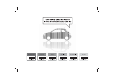
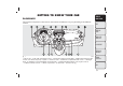
GETTING TO KNOW YOUR CAR GETTING TO KNOW YOUR CAR DASHBOARD The presence and position of the controls, instruments and indicators may vary according to the different versions. SAFETY STARTING AND DRIVING WARNING LIGHTS AND MESSAGES IN AN EMERGENCY SERVICING AND MAINTENANCE fig. 1 F0S0390 1. Side air vent – 2. Left stalk: external light control – 3. Instrument panel and warning lights – 4. Right stalk: windscreen wiper controls, rear window wiper, trip computer – 5. Centre air vents – 6.
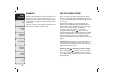
GETTING TO KNOW YOUR CAR SAFETY STARTING AND DRIVING WARNING LIGHTS AND MESSAGES IN AN EMERGENCY SERVICING AND MAINTENANCE TECHNICAL SPECIFICATIONS INDEX 4 SYMBOLS THE FIAT CODE SYSTEM Special coloured labels have been attached near or actually on some of the components of your car. These labels bear symbols that remind you of the precautions to be taken as regards that particular component. The inner surface of the engine bonnet includes a label with the different symbols used.
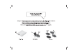
THE KEYS CODE CARD (for versions/markets, where provided) The car is delivered with two copies of the ignition key and with the CODE card which bears the following: A fig. 2 the electronic code; B fig. 2 the mechanical key code to be given to the Fiat Dealership when ordering duplicate keys. You should have the electronic code A with you at all times. IMPORTANT All the keys and the CODE card must be handed over to the new owner when selling the car.
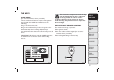
GETTING TO KNOW YOUR CAR SAFETY STARTING AND DRIVING WARNING LIGHTS AND MESSAGES KEY WITH REMOTE CONTROL (for versions/markets, where provided) Locking the doors and the tailgate The metal insert A fig. 4 operates: ❒ the ignition switch; ❒ the door locks; ❒ the locking/unlocking of the fuel cap. Press button B fig. 4 to open/close the metal insert.
REPLACING REMOTE CONTROL BATTERY To replace the battery, proceed as follows: ❒ press button A fig. 5 and open the metal insert B fig. 5; ❒ turn the screw C fig. 5 to using a fine bit screwdriver; ❒ take out the battery case D fig. 5 and replace the battery E fig. 5 making sure that polarities are correct; ❒ refit the battery case D inside the key and lock it turning the screw C to . REPLACING THE REMOTE CONTROL COVER Proceed as shown in fig. 6 and fig. 7 to replace the remove control cover.
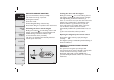
GETTING TO KNOW YOUR CAR SAFETY STARTING AND DRIVING WARNING LIGHTS AND MESSAGES IGNITION DEVICE STEERING LOCK The key can be turned to 3 different positions fig. 8: ❒ STOP: engine off, key can be removed, steering column locked. Some electrical devices (e.g. sound system, central door locking system, etc.) can operate; ❒ MAR-ON: driving position. All electrical devices are enabled; ❒ AVV: engine start-up.
CONTROL PANEL AND INSTRUMENTS The instrument background colour and type may vary according to the versions. Diesel versions have a rev counter with 6 rpm x 1000 full scale. The warning lights The warning light and or are only present on Diesel versions. GETTING TO KNOW YOUR CAR SAFETY is available only on versions with Dualogic gearbox (see “Dualogic” supplement). STARTING AND DRIVING WARNING LIGHTS AND MESSAGES IN AN EMERGENCY SERVICING AND MAINTENANCE TECHNICAL SPECIFICATIONS fig. 9 A.
GETTING TO KNOW YOUR CAR SPEEDOMETER (SPEED INDICATOR) REV COUNTER The indicator A fig. 10-fig. 11 shows the car speed (speedometer). The indicator B fig. 10-fig. 11 shows the engine revs. Full scale 8 rpm x 1000: petrol versions. Full scale 6 rpm x 1000: diesel versions. SAFETY DIGITAL FUEL LEVEL INDICATOR The digital gauge C fig. 10 - fig. 11 shows the amount of fuel in the tank. The warning light E fig. 10 - fig. 11 switches on to indicate that approximately 5 litres of fuel are left in the tank.
MULTIFUNCTION DISPLAY The car may be equipped with a multifunction display that, according to previous settings, will show useful driving information. GEAR SHIFT INDICATOR (for versions/markets, where provided) Shift up Shift down On vehicles with a manual gearbox, the gear shift indicator suggests gear changes to the driver (SHIFT UP or SHIFT DOWN) via a special display on the control panel. This suggestion to change gear is designed to improve consumption and ensure the best driving style.
GETTING TO KNOW YOUR CAR SAFETY STARTING AND DRIVING WARNING LIGHTS AND MESSAGES IN AN EMERGENCY Note When one of the front doors is opened, the display is activated showing the time and km/mileage (for markets/versions, where provided) for a few seconds. MULTIFUNCTION DISPLAY “STANDARD” SCREEN The standard screen fig. 13 shows the following information: 1 Odometer (display of distance travelled in kilometres/miles) 2 SPORT driving mode indication (0.
❒ SET TIME ❒ SET DATE ❒ SEE RADIO ❒ AUTOCLOSE ❒ MEASUREMENT UNIT ❒ LANGUAGE ❒ BUZZER VOLUME ❒ BUTTON VOLUME ❒ BELT BUZZER ❒ SERVICE ❒ PASSENGER AIRBAG ❒ DAYTIME RUNNING LIGHTS ❒ EXIT MENU Selecting an option from the main menu without a submenu: ❒ briefly press the MENU button to select the main menu option to be set; ❒ press buttons + or – (with single presses) to select the new setting; ❒ briefly press the MENU button to store the new setting and to go back to the same main menu option selected previously
GETTING TO KNOW YOUR CAR SAFETY STARTING AND DRIVING WARNING LIGHTS AND MESSAGES IN AN EMERGENCY SERVICING AND MAINTENANCE TECHNICAL SPECIFICATIONS INDEX 14 For versions/markets, where provided, during the daytime, and with the dipped headlamps on, the instrument panel, buttons and sound system and automatic climate control displays are set to maximum brightness.
❒ press button + or – to set; ❒ press the MENU button briefly to return to the menu screen or hold the button down to return to the standard screen without storing. Time adjustment (Clock adjustment) This function enables to set the clock through two sub-menus: “Time” and “Format”.
GETTING TO KNOW YOUR CAR SAFETY Note The setting will increase or decrease by one unit each time the button + or – is pressed. Hold down the button to increase/decrease the setting rapidly and automatically. Complete the setting by briefly pressing the button when you approach the required value. ❒ press the MENU button briefly to return to the menu screen or hold the button down to return to the standard screen without storing.
❒ press the button + or – to switch between the two submenus; ❒ once you have selected a submenu, press the MENU button briefly; ❒ when you select “Distances”, briefly pressing the MENU button makes the display show "km" or "mi" depending on the previous setting; ❒ press button + or – to set; ❒ when you select “Consumption”, briefly pressing the MENU button makes km/l, l/100km or mpg appear on the display depending on the previous setting; If the set distance unit is "km", the fuel consumption unit will be
GETTING TO KNOW YOUR CAR SAFETY STARTING AND DRIVING ❒ press + or – to set the value; ❒ press the MENU button briefly to return to the menu screen or hold the button down to return to the standard screen without storing. Belt buzzer (Buzzer activation for S.B.R. indication) This function can only be displayed after a Fiat Dealership has deactivated the SBR system (see “SBR system” in the “Safety” section).
❒ press buttons + or – to select (Yes) (confirming activation/deactivation) or (No) (to abort); briefly, a message ❒ press the MENU button confirming the selection will be displayed and you will return to the menu screen or hold the button down to return to the standard screen without storing. Exit menu This function closes the cycle of settings listed in the menu screen. briefly will return the Pressing the MENU button display to the standard screen without storing.
GETTING TO KNOW YOUR CAR SAFETY STARTING AND DRIVING WARNING LIGHTS AND MESSAGES IN AN EMERGENCY SERVICING AND MAINTENANCE TECHNICAL SPECIFICATIONS INDEX 20 TRIP COMPUTER Values displayed General information Range The Trip computer is used to display information on car operation when the key is turned to MAR. This function is composed of separate trips, called “Trip A” and “Trip B” which can monitor the entire mission (journey) in a reciprocally independent manner.
Average speed New mission This value shows the car's average speed based on the overall time elapsed since the start of the new journey. It begins after a reset: ❒ “manual” resetting by the user, by pressing the relevant button; ❒ “automatic” resetting, when the “Trip distance” reaches 9999.9 km or when the “Travel time” reaches 99:59 (99 hours and 59 minutes); ❒ disconnection/reconnection of the battery. Journey time Time elapsed since the start of the new journey.
GETTING TO KNOW YOUR CAR SAFETY FRONT SEATS WARNING WARNING All adjustments must be made with the car stationary. Once you have released the adjustment lever, always check that the seat is locked on the guides by trying to move it back and forth. Failure to lock the seat in place could result in the seat moving suddenly and the driver losing control of the car. LENGTHWISE DIRECTION ADJUSTMENT STARTING AND DRIVING Lift the lever A fig.
HEIGHT ADJUSTMENT (for versions/markets, where provided) Operate lever C fig. 17 to lift or lower the rear part of the cushion to achieve the most comfortable driving position. BACKREST FOLDING To fold the backrest over, adjust lever D fig. 18 (movement 1) and push the backrest forwards until it locks (movement 2); release lever D and, pushing the backrest, slide the seat forwards (movement 3).
GETTING TO KNOW YOUR CAR SAFETY STARTING AND DRIVING PASSENGER SIDE WITHOUT POSITION MEMORY REAR SEATS To restore the seat to its original position, slide the seat backwards pushing the backrest until the desired position is reached (movement 4), adjust lever D fig. 18 (movement 5) and raise the backrest (movement 6) until the locking can be heard. The type of reattachment manoeuvre has been chosen to guarantee the safety of the occupant. If an obstacle is present (e.g.
HEAD RESTRAINTS WARNING FRONT Head restraints are height-adjustable; to adjust them operate as follows. Upwards adjustment: lift the head restraint until it locks. Downwards adjustment: press the button A fig. 20 and lower the head restraint. WARNING All adjustments must be carried out only with the vehicle stationary and engine off. Head restraints must be adjusted so that the head, rather than the neck, rests on them. Only in this case can they protect your head correctly.
GETTING TO KNOW YOUR CAR SAFETY To lower the head restraint press button B. The particular head restraint shape deliberately interferes with the passenger correctly supporting their back on the backrest in order to force them to lift the head restraint and use it correctly. IMPORTANT If the rear seats are used, always set the head restraints in the "completely raised" position. STEERING WHEEL ADJUSTMENT (for versions/markets, where provided) The steering wheel can be adjusted vertically.
INTERIOR REAR VIEW MIRROR The mirror is fitted with a safety device that causes its release in the event of a violent impact with the passenger. Lever A fig. 23 can be used to move the mirror to two different positions: normal or antiglare. ELECTROCHROMIC INTERIOR MIRROR (for versions/markets, where provided) Some versions have an electrochromic mirror with automatic antiglare function. There is an ON/OFF button on the lower part of the mirror for activating/deactivating the electrochromic function.
FOLDING THE MIRRORS GETTING TO KNOW YOUR CAR When required (for example when the mirror causes difficulty in narrow spaces) it is possible to fold the mirrors by moving them from position 1 fig. 25 (open), to position 2 fig. 25 (closed). SAFETY STARTING AND DRIVING WARNING LIGHTS AND MESSAGES IN AN EMERGENCY SERVICING AND MAINTENANCE TECHNICAL SPECIFICATIONS INDEX 28 fig. 25 F0S0035 WARNING As door mirrors are curved, they may slightly alter the perception of distance.
TEMPERATURE COMFORT GETTING TO KNOW YOUR CAR VENTS SAFETY STARTING AND DRIVING WARNING LIGHTS AND MESSAGES IN AN EMERGENCY SERVICING AND MAINTENANCE fig. 26 F0S0021 1. Vents for defrosting or demisting the windscreen – 2. Adjustable centre vents – 3. Adjustable side vents – 4. Fixed vents for side windows – 5.
GETTING TO KNOW YOUR CAR SAFETY STARTING AND DRIVING WARNING LIGHTS AND MESSAGES IN AN EMERGENCY SERVICING AND MAINTENANCE TECHNICAL SPECIFICATIONS HEATING AND VENTILATION ADDITIONAL HEATER (for versions/markets, where provided) This device speeds up passenger compartment warming when it is very cold. The additional heater turns off automatically after reaching the required comfort conditions. Important The heater only works if the outside temperature and engine coolant temperature are low.
Fast front window demisting/defrosting Proceed as follows: ❒ turn knob A to the red section; ❒ turn knob C to ; ❒ turn knob D to ; ❒ turn knob B to 4 (maximum fan speed). MANUAL CLIMATE CONTROL (for versions/markets, where provided) The additional heater is activated automatically by turning knob A to the end of the red section and setting the fan (knob B) to at least the 1st speed CONTROLS A Air temperature knob (red = hot/blue = cold) fig.
GETTING TO KNOW YOUR CAR SAFETY STARTING AND DRIVING WARNING LIGHTS AND MESSAGES IN AN EMERGENCY SERVICING AND MAINTENANCE TECHNICAL SPECIFICATIONS INDEX 32 C Air recirculation knob fig. 28 internal air recirculation air intake from outside IMPORTANT It is advisable to switch the air recirculation on whilst queueing or in tunnels to prevent the introduction of polluted air.
AUTOMATIC CLIMATE CONTROL (for versions/markets, where provided) The additional heater turns on automatically depending on the environmental conditions and with engine started when the temperature of the engine coolant is low. It is turned off also automatically after reaching the required comfort conditions in the passenger compartment and when the engine coolant temperature is hot. According to the temperature set by the user, the automatic climate control system fig.
GETTING TO KNOW YOUR CAR SAFETY STARTING AND DRIVING WARNING LIGHTS AND MESSAGES IN AN EMERGENCY SERVICING AND MAINTENANCE TECHNICAL SPECIFICATIONS INDEX 34 ❒ it is not possible to convey air to the passenger compartment with a temperature below the outside temperature (the displayed temperature value will flash when the system cannot guarantee the required comfort conditions); ❒ the fan speed can be manually reset (with compressor enabled, ventilation cannot go below a bar shown on the display).
G H I buttons fig. 29 of air distribution - Manual selection By pressing the buttons, one of the five possible air flow distribution patterns can be selected: air flow to the windscreen and front side window vents to demist or defrost them. air flow to central and side dashboard vents to ventilate the chest and the face during the hot season. air flow towards the front seat feet area.
GETTING TO KNOW YOUR CAR SAFETY STARTING AND DRIVING WARNING LIGHTS AND MESSAGES IN AN EMERGENCY SERVICING AND MAINTENANCE TECHNICAL SPECIFICATIONS INDEX 36 The system uses R134a refrigerant fluid which does not pollute the environment in the event of accidental leakage. Never use R12 fluid, which is not compatible with the system components. HEATED REAR WINDOW DEMISTING/DEFROSTING Press button to activate this function. Activation is indicated by switching on of warning light on the instrument panel.
WARNING Daytime running lights cannot replace dipped beam headlights when driving at night or through tunnels.The use of daytime running lights is governed by the highway code of the country in which you are driving. Comply with legal requirements. DIPPED BEAM HEADLIGHTS/SIDE LIGHTS With the ignition key turned to MAR-ON, turn the twist switch to fig. 30. If dipped beam headlights are activated, the daytime running lights go out and the side and tail lights and dipped beam headlights come on.
GETTING TO KNOW YOUR CAR SAFETY STARTING AND DRIVING WARNING LIGHTS AND MESSAGES Lane change function If you wish to signal a lane change, put the left stalk in the temporary position for less than half a second. The direction indicator on the selected side flashes three times and then switches off automatically. "FOLLOW ME HOME" DEVICE This allows the space surrounding the car to be lit up for a certain period of time.
WINDOW CLEANING The right stalk controls windscreen wiper/washer and heated rear window wiper/washer operation. WINDSCREEN WASHER/WIPER This operates only with the ignition key turned to MAR-ON. The stalk has 5 different positions (4 speeds)fig. 32: A. windscreen wiper off. B. intermittent operation. C. continuous slow operation. D. continuous fast operation. E. temporary fast operation (unstable position). The temporary fast function lasts as long as you manually keep the stalk in that position.
GETTING TO KNOW YOUR CAR SAFETY STARTING AND DRIVING WARNING LIGHTS AND MESSAGES IN AN EMERGENCY SERVICING AND MAINTENANCE TECHNICAL SPECIFICATIONS INDEX 40 With the windscreen wiper on, engaging reverse gear will automatically turn the rear window wiper on, in continuous slow operation. Operation stops when reverse is disengaged. "Smart washing" function: push the stalk towards the dashboard (unstable position) to operate the rear window washer.
Three modes are provided for switching off: ❒ when all doors are closed, the 3-minute timer will stop and a 10-second one will start. This timer will stop when the key is turned to MAR-ON; ❒ when doors are locked (either with remote control or with key on driver side door), the roof light turns off.
GETTING TO KNOW YOUR CAR SAFETY STARTING AND DRIVING WARNING LIGHTS AND MESSAGES IN AN EMERGENCY When this function is active, the wording ECO on the instrument panel will turn on. This function is stored and, at the next starting, the system keeps the setting it had before the engine was shut down. The E button should be pressed again to turn the function off and restore the normal driving setting. The D button should be pressed again to turn the function off and restore the normal driving setting.
Emergency braking In the event of an emergency braking, the hazard warning light switch on automatically together with warning lights and on the instrument panel. The function switches off automatically when the nature of the braking changes. This function complies with the relevant legislations currently in force. REAR FOG LIGHTS (for versions/markets, where provided) To turn the lights on press the button D fig. 36 with the dipped beam headlights on.
GETTING TO KNOW YOUR CAR INTERIOR FITTINGS The passenger side sun visor includes a courtesy mirror, lighted by a specific roof light that can be switched on using the button B fig. 37. CIGAR LIGHTER (for versions/markets, where provided) WARNING WARNING SAFETY STARTING AND DRIVING WARNING LIGHTS AND MESSAGES The cigar lighter gets very hot. Handle it carefully and make sure that children don't touch it: risk of fire and/or burns. Always check that the cigar lighter is switched off.
COMPARTMENT IN CENTRAL CONSOLE To open the compartment, use the groove B fig. 39 and pull outwards. WARNING Never travel with the compartment open: it could injure the passenger in the event of a crash. GETTING TO KNOW YOUR CAR SAFETY STORAGE COMPARTMENT UNDER THE SEAT (for versions/markets, where provided) fig. 38 F0S0040 In some versions, there is a storage compartment fig. 40 under the passenger seat. To access the storage compartment, lift the front area of the cushion 1 fig.
CUP/BOTTLE HOLDERS GETTING TO KNOW YOUR CAR SAFETY STARTING AND DRIVING WARNING LIGHTS AND MESSAGES IN AN EMERGENCY On the central tunnel there are two cup/can holders for the front seats and two for the rear seats. Accessories with a maximum power of 180 W (maximum electrical input 15 A) can be connected to the socket.
FIXED GLASS ROOF SUN ROOF The sun roof comprises a wide fixed glass panel and a manually-operated sun blind. The blinds can be used in the "fully closed" or "fully open" positions. To open the blind, grab the handle, press the tooth A fig. 43 and move it to the completely open position. To close it, grab the handle and move the blind to the closing position until tooth A is attached. The sun roof comprises a wide electrically-operated glass panel and a manually-operated sun blind.
OPENING GETTING TO KNOW YOUR CAR SAFETY Keep the button B fig. 45 pressed: the roof will move to "spoiler" position. To fully open the roof press the button B again and keep it pressed: the roof will stop in the position reached when the button is released. CLOSURE STARTING AND DRIVING WARNING LIGHTS AND MESSAGES Keep the button A fig. 45 pressed: the roof will move to "spoiler" position. The roof will stop in the position reached when the button is released.
Proceed as follows: ❒ keep the button A fig. 45 pressed so that the roof closes completely in stages ❒ after full closing, wait for the sun roof motor to stop. EMERGENCY OPERATION If the electric device for moving the roof fails, the sun roof can be moved manually proceeding as described below: ❒ for manual activation remove the protective cap A fig.
WARNING LIGHTS AND MESSAGES To lock from outside: with driver's side door completely closed, turn the key to position 2 fig. 48. It is possible to lock the passenger side door only from inside bringing the handle to position 2 fig. 48. On versions with central locking, when the key is turned, the doors and the tailgate are simultaneously locked. To lock/unlock from inside: use the handles on the door panels fig. 48. Position 1: the door is unlocked. Position 2: the door is locked.
To lock from inside (door and tailgate locks) push handle A towards door panel. Operating the lever on driver or passenger side locks both doors and tailgate. The correct lever position with locked doors is shown by the red symbol B fig. 49 visible on the handles. POWER WINDOWS GETTING TO KNOW YOUR CAR POWER WINDOWS (for versions/markets, where provided) These operate when the ignition key is turned to MAR-ON and for about 2 minutes after turning the key to STOP or removing it.
GETTING TO KNOW YOUR CAR SAFETY STARTING AND DRIVING WARNING LIGHTS AND MESSAGES IN AN EMERGENCY SERVICING AND MAINTENANCE WARNING Incorrect use of the power windows may be dangerous. Before and during operation, always check that no-one is exposed to the risk of being injured either directly by the moving window or through objects getting caught and being dragged.
OPENING THE TAILGATE WITH THE REMOTE CONTROL (for versions/markets, where provided) Press button on the key with the remote control. The direction indicators will blink twice when the tailgate is opened. SOFT TOUCH POWER HANDLE (for versions/markets, where provided) On some versions, the tailgate (if released) can be opened only from outside the car operating on the power handle B fig. 52 located under the tailgate edge. The boot can be opened at any time if the doors are unlocked.
GETTING TO KNOW YOUR CAR SAFETY STARTING AND DRIVING WARNING LIGHTS AND MESSAGES IN AN EMERGENCY SERVICING AND MAINTENANCE WARNING Never exceed the maximum allowed load in the boot (see "Technical Specifications"). Also make sure that the objects you place in the boot have been properly secured, to avoid them from being thrown forward consequent to sudden braking and injuring your passengers.
EXTENDING THE BOOT The separate rear seats allow partial fig. 55 or total fig. 56 boot extension. PARTIAL EXTENSION (50/50) (for versions/markets, where provided) Proceed as follows: ❒ lift out rear seat head restraints (where provided) with backrest released and tilted toward the passenger compartment or with the tailgate open ❒ check that the seat belt is fully extended and not twisted ❒ operate lever A fig.
GETTING TO KNOW YOUR CAR SAFETY STARTING AND DRIVING WARNING LIGHTS AND MESSAGES IN AN EMERGENCY SERVICING AND MAINTENANCE TECHNICAL SPECIFICATIONS INDEX 56 Proceed as follows: ❒ remove the rear seat head restraints (where provided) ❒ check that the seat belts are correctly extended and not twisted ❒ operate the levers A fig. 57 and B to release the backrests and guide them down onto the cushion.
WARNING The bonnet may drop suddenly if the supporting rod is not positioned properly. Only perform these operations when the car is stationary. Before opening the bonnet, check that windscreen wiper arm is not lifted from the windscreen. WARNING When the engine is warm, work carefully inside the engine compartment to avoid getting burnt. Do not place your hands close to the fan: it might start working even with the ignition key removed.Wait for the engine to cool. WARNING fig.
ROOF RACK/SKI RACK CLOSURE GETTING TO KNOW YOUR CAR SAFETY STARTING AND DRIVING WARNING LIGHTS AND MESSAGES IN AN EMERGENCY SERVICING AND MAINTENANCE Proceed as follows: ❒ hold the bonnet up with one hand and with the other remove rod C fig. 60 from housing E and fit it back into its catch D ❒ lower the bonnet to approximately 20 centimetres above the engine compartment and let it come down. Make sure that the bonnet is completely closed and not just secured in safety position.
HEADLIGHTS WARNING Fully comply with the regulations in force concerning maximum clearance. Never exceed the maximum permitted loads; see section "Technical specifications". WARNING Evenly distribute the load and take into account, when driving, the increased responsiveness of the car to side wind. Check that the attachment fixing screws are tight after a few kilometres.
GETTING TO KNOW YOUR CAR SAFETY STARTING AND DRIVING WARNING LIGHTS AND MESSAGES The display provides a visual indication of the positions during adjustment. Gas discharge headlights (Xenon headlights) are automatically adjusted. Headlight alignment adjustment is electronic and therefore cannot be manually adjusted using the + and – buttons. Correct positions depending on the load Position 0 - one or two people in the front seats. Position 1 - four persons.
ABS SYSTEM WARNING This system, which is an integral part of the braking system, prevents one or more wheels from locking and slipping on all road surface conditions, irrespective of the intensity of the braking action, ensuring that the car can be controlled even during emergency braking thus optimising stopping distances. The system intervenes when braking and the wheels are about to lock, typically in emergency braking or low-grip conditions, when locking may be more frequent.
GETTING TO KNOW YOUR CAR SAFETY WARNING The capability of the ABS must never be tested irresponsibly and dangerously, in such a way as to compromise personal safety and the safety of others. EBD (Electronic Brakeforce Distribution) SYSTEM This system, which cannot be deactivated, recognises emergency braking conditions (according to the brake pedal operation speed) and provides an additional hydraulic braking pressure to support that provided by the driver.
ESC (Electronic Stability Control) SYSTEM This is an electronic system that controls car stability in the event of tyre grip loss, helping maintain directional control. The system is capable of recognising potentially dangerous situations in terms of the stability and intervenes automatically on the brakes in a differentiated manner for the four wheels in order to provide a stabilising torque.
GETTING TO KNOW YOUR CAR SAFETY STARTING AND DRIVING WARNING LIGHTS AND MESSAGES IN AN EMERGENCY SERVICING AND MAINTENANCE TECHNICAL SPECIFICATIONS INDEX 64 WARNING There may be situations on small gradients (less than 8%), with car laden or a trailer attached to it (where provided), in which the HH system may not activate, causing a slight reversing motion and increasing the risk of collision with another vehicle or object. The driver is, in any case, responsible for safe driving.
WARNING For the correct operation of the ASR system, it is essential that the tyres are of the same make and type on all wheels, in perfect condition and, above all, of the specified type and dimensions. WARNING If the space-saver wheel (where provided) is used, the ASR system keeps operating. Always remember that the space-saver wheel, being smaller than the original wheel, provides less grip.
GETTING TO KNOW YOUR CAR SAFETY WARNING The HBA system cannot increase tyre grip on the road over the limits imposed by laws of physics: always drive carefully according to the conditions of the road surface. WARNING STARTING AND DRIVING WARNING LIGHTS AND MESSAGES The HBA system cannot prevent accidents, including those due to excessive speed on bends, travelling on low-grip surfaces or aquaplaning.
If, when the ignition key is turned to the MAR-ON position, the warning light either does not come on or, when driving, it comes on permanently or flashes along with a message in the multifunction display (for versions/markets where provided), contact a Fiat Dealership as soon as possible.The operation of warning light may be checked by the traffic police using specific devices. Comply with the laws and regulations of the country where you are driving.
GETTING TO KNOW YOUR CAR SAFETY STARTING AND DRIVING WARNING It is absolutely forbidden to carry out any after-market operation involving steering system or steering column modifications (e.g.: installation of anti-theft device) that could badly affect performance and safety, invalidate warranty and also result in non-compliance of the car with type approval requirements.
PARKING SENSORS (for versions/markets, where provided) Parking sensors are located in the rear bumper fig. 66 and their function is to inform the driver, through an intermittent buzzer, about the presence of obstacles behind the car. ACTIVATION The sensors are automatically activated when the reverse gear is engaged. As the obstacle behind the vehicle gets closer to the car, the buzzer becomes more frequent.
GETTING TO KNOW YOUR CAR SAFETY STARTING AND DRIVING WARNING LIGHTS AND MESSAGES IN AN EMERGENCY SERVICING AND MAINTENANCE TECHNICAL SPECIFICATIONS INDEX 70 For correct operation, sensors must always be clean from mud, dirt, snow or ice. Be careful not to scratch or damage the sensors while cleaning them. Avoid using dry, rough or hard cloths.The sensors should be washed using clean water with the addition of car shampoo if necessary.
START&STOP SYSTEM INTRODUCTION The Start&Stop system automatically stops the engine each time the vehicle is stationary and starts it again when the driver wants to move off. In this way, the vehicle efficiency is increased, by reducing consumption, dangerous gas emissions and sound pollution. Note If the climate comfort is to be favoured, the Start&Stop system can be deactivated, for a continuous operation of the climate control system. The engine stop is signalled by the warning light fig.
GETTING TO KNOW YOUR CAR SAFETY STARTING AND DRIVING MANUAL ACTIVATION AND DEACTIVATION The system can be activated/deactivated using the button A fig. 68 on the dashboard. When the system is deactivated, the warning light fig. 69 switches on on the instrument panel. In addition, for versions/markets where provided, additional indications concerning the deactivation or activation of Start&Stop system are given on the display.
ENGINE RESTARTING CONDITIONS For reasons of comfort, limiting harmful emissions and safety purposes, the power unit can restart automatically without any action by the driver if certain conditions are met, including: ❒ battery not sufficiently charged ❒ reduced braking system vacuum (e.g. if the brake pedal is pressed repeatedly) ❒ car moving (e.g.
IRREGULAR OPERATION GETTING TO KNOW YOUR CAR SAFETY STARTING AND DRIVING WARNING LIGHTS AND MESSAGES IN AN EMERGENCY In the case of malfunctions the Start&Stop system is disabled. The driver is informed of the problem by the general failure warning light A fig. 70 switching on with an information message (where provided) and the system failure symbol B fig. 70 in the instrument panel. Contact a Fiat Dealership.
EMERGENCY STARTING IMPORTANT NOTES When jump starting, never connect the negative lead – fig. 72 of the auxiliary battery to the negative pole A fig. 72 of the car battery, rather to an engine/gearbox earth point. GETTING TO KNOW YOUR CAR WARNING Before opening the bonnet, make sure that the vehicle is switched off and the key is in the STOP position. Follow the instructions on the dedicated label on the front crossmember fig. 73.
GETTING TO KNOW YOUR CAR SAFETY STARTING AND DRIVING WARNING LIGHTS AND MESSAGES WARNING For cars with Dualogic gearbox, if the engine is automatically stopped on a slope, the engine should be restarted by moving the gear lever to + or – without releasing the brake pedal.
SETUP (for versions/markets, where provided) In addition to the standard equipment the vehicle also features: ❒ two 165 mm diameter 40 W mid-woofer speakers, in one of the front doors ❒ two 38 mm diameter 30 W tweeter speakers, in the front pillars ❒ aerial supply cable ❒ front speaker power cables ❒ radio supply cables ❒ roof-mounted aerial.
GETTING TO KNOW YOUR CAR SAFETY STARTING AND DRIVING WARNING LIGHTS AND MESSAGES IN AN EMERGENCY SERVICING AND MAINTENANCE ACCESSORIES PURCHASED BY THE OWNER If after buying the car, you decide to install electrical accessories that require a permanent electric supply (alarm, satellite antitheft system, etc.
AT THE FILLING STATION PETROL ENGINES Use unleaded petrol only, with octane number (R.O.N.) not lower than 95. IMPORTANT An inefficient catalytic converter leads to harmful exhaust emissions, thus contributing to air pollution. IMPORTANT Never use leaded petrol, even in small amounts or in an emergency, as this would damage the catalytic converter beyond repair.
GETTING TO KNOW YOUR CAR SAFETY FUEL CUT-OFF SYSTEM WARNING Do not bring open flames or lit cigarettes near to the fuel tank opening: fire risk. Keep your face away from the fuel filler to prevent breathing in harmful vapours. STARTING AND DRIVING IMPORTANT Carefully check the car for fuel leaks, for instance in the engine compartment, under the car or near the tank area. After a collision, turn the ignition key to STOP position to prevent the battery from running down.
❒ turn the ignition key to the STOP position ❒ turn the ignition key to the MAR-ON position. WARNING If, after an impact, you smell fuel or notice leaks from the fuel system, do not reactivate the system to avoid the risk of fire. PROTECTING THE ENVIRONMENT The following devices are used for reducing petrol fuel engine emissions: ❒ three-way catalytic converter (catalytic converter) ❒ oxygen sensors ❒ evaporation control system.
GETTING TO KNOW YOUR CAR SAFETY STARTING AND DRIVING WARNING LIGHTS AND MESSAGES IN AN EMERGENCY SERVICING AND MAINTENANCE TECHNICAL SPECIFICATIONS INDEX 82 DIESEL PARTICULATE FILTER (DPF) (MultiJet versions with DPF only) The Diesel Particulate Filter is a mechanical filter, integral with the exhaust system, that physically traps particulates present in the exhaust gases of diesel engines.
SAFETY SEAT BELTS GETTING TO KNOW YOUR CAR WARNING Never press button C when travelling. USING THE SEAT BELTS The belt should be worn keeping the torso straight and rested against the backrest. To fasten the seat belts, hold the tongue A fig. 76 and insert it into the buckle B fig. 76, until it clicks into place. On removal, if it jams, let it rewind for a short stretch, then pull it out again without jerking. To unfasten seat belts, press button C fig. 76.
GETTING TO KNOW YOUR CAR SAFETY STARTING AND DRIVING WARNING LIGHTS AND MESSAGES IN AN EMERGENCY SERVICING AND MAINTENANCE TECHNICAL SPECIFICATIONS INDEX 84 SBR SYSTEM PRETENSIONERS The car is provided with the SBR (Seat Belt Reminder) system, which warns the driver and the front passenger if their seat belts are not fastened, as follows: ❒ warning light switched on constantly and continuos beep for the first 6 seconds; ❒ warning light flashes and intermittent beep for the next 96 seconds.
Operations which lead to impacts, vibrations or localised heating (over 100°C for a maximum of six hours) in the area around the pretensioner may damage or deploy it. Contact a Fiat Dealership should intervention be necessary on these components. LOAD LIMITERS To increase occupant safety, the retractors of the safety belts contain a load limiter to dose the force acting on the chest and shoulders during the belt restraining action in the case of frontal collisions.
GETTING TO KNOW YOUR CAR SAFETY STARTING AND DRIVING IMPORTANT The seat belt must not be twisted. The upper part must pass over the shoulder and cross the chest diagonally. The lower part must adhere to the pelvis (as shown in fig. 78) rather than the abdomen of the occupant. Never use devices (clips, clamps, etc.) to hold the seat belt away from your body. IMPORTANT Each seat belt must be used by only one person.
❒ replace the belt after an accident of a certain severity even if it does not appear to be damaged. Always replace the seat belt if the pretensioners were deployed; ❒ to clean the seat belts, wash by hand with water and neutral soap, rinse and leave to dry in the shade.
GETTING TO KNOW YOUR CAR SAFETY STARTING AND DRIVING WARNING LIGHTS AND MESSAGES IN AN EMERGENCY SERVICING AND MAINTENANCE TECHNICAL SPECIFICATIONS Group Weight groups Group 0 up to 10 kg of weight Group 0+ up to 13 kg of weight Group 1 9-18 kg in weight Group 2 15-25 kg in weight Group 3 22-36 kg of weight All child restraint devices must bear the certification data, together with the control mark, on a label solidly fixed to the seat which must never be removed.
GROUP 2 WARNING The figures are only examples for fitting purposes.To install the child restraint system, refer to the instructions supplied with the same. GROUP 1 Children from 15 to 25 kg may use the car seat belts directly fig. 82. The child restraint system is used only to position the child correctly with respect to the belts so that the diagonal section crosses the child's chest and never the neck, and the lower part is snug on the pelvis not the abdomen.
GROUP 3 GETTING TO KNOW YOUR CAR SAFETY WARNING For children from 22 kg up to 36 kg suitable risers are available to position the seat belt correctly. The fig. 83 shows the correct child restraint system positioning on the rear seat. Children over 1.50 m in height can wear seat belts like adults. STARTING AND DRIVING WARNING LIGHTS AND MESSAGES IN AN EMERGENCY SERVICING AND MAINTENANCE TECHNICAL SPECIFICATIONS INDEX 90 fig. 83 F0S0084 The figures are only examples for fitting purposes.
PASSENGER SEAT COMPLIANCE FOR USING UNIVERSAL CHILD RESTRAINT SYSTEMS complies with the European Directive 2000/3/EC which governs the arrangement possibilities The Fiat for child restraint systems on the various seats of the car as shown in the following table: Group Weight groups Front passenger seat Rear passenger seat up to 13 kg U U Group 1 9-18 kg U U Group 2 15-25 kg U U Group 3 22-36 kg Group 0, 0+ U U U= suitable for child restraint systems of the "Universal" category, according t
GETTING TO KNOW YOUR CAR SAFETY UNIVERSAL ISOFIX CHILD RESTRAINT SYSTEM ASSEMBLY SETUP The car is equipped with ISOFIX anchorages, a new European standard which makes fitting a child restraint system quick, simple and safe. STARTING AND DRIVING WARNING LIGHTS AND MESSAGES Traditional child restraint systems can be fitted alongside Universal Isofix child restraint systems. An example of Universal Isofix child restraint system covering weight group 1 is shown in fig. 84.
Remember that, in the case of Universal Isofix child restraint systems, you can use all restraint systems bearing the marking ECE R44 (R44/03 or later updates) "Universal Isofix". WARNING If a Universal Isofix child restraint system is not fixed to all three anchorages, the child restraint system will not be able to protect the child correctly. In a crash, the child could be seriously or fatally injured.
GETTING TO KNOW YOUR CAR SAFETY PASSENGER SEAT COMPLIANCE FOR USING UNIVERSAL ISOFIX CHILD RESTRAINT SYSTEMS The table below shows the different installation possibilities of Universal Isofix restraint systems on the seats fitted with Isofix fasteners, in accordance with European standard ECE 16.
AIR BAG The car is provided with front airbags for the driver and the passenger, driver's knee bag (for versions/ markets, where provided), front side bags (for versions/markets, where provided) and window bags. FRONT AIR BAGS The front driver/passenger airbags and the driver's knee bag (for versions/markets, where provided) protect the front seat occupants in the event of frontal impacts of medium/high severity, by placing the bag between the occupant and the steering wheel or dashboard.
GETTING TO KNOW YOUR CAR SAFETY STARTING AND DRIVING WARNING LIGHTS AND MESSAGES Their volume at the moment of maximum inflation fills most of the space between the steering wheel and the driver, between the lower post guard and the knees on passenger side and between the dashboard and the passenger. The airbags are not deployed in the event of minor frontal collisions (for which the restraining action of the seat belts is sufficient). Safety belts must always be worn.
WARNING SEVERE DANGER:When an active passenger airbag is fitted, DO NOT install rearward facing child restraints on the front seat. Deployment of the airbag in an accident could cause fatal injuries to the child regardless of the severity of the impact.Therefore, always deactivate the passenger airbag when a rearward facing child restraint system is installed on the front passenger seat.
Passenger front airbag and child restraint system:WARNING GETTING TO KNOW YOUR CAR SAFETY STARTING AND DRIVING WARNING LIGHTS AND MESSAGES IN AN EMERGENCY SERVICING AND MAINTENANCE TECHNICAL SPECIFICATIONS INDEX fig.
Driver's side knee bag (for versions/markets, where provided) It consists of an instantly inflating cushion housed into a special compartment under the lower post guard fig. 90 at driver's knee level, designed to give further protection in the event of a head-on crash.
GETTING TO KNOW YOUR CAR IMPORTANT In the event of a side impact, the system provides best protection if the passenger sits on the seat in a correct position, thus allowing correct window bag deployment. SAFETY IMPORTANT A small amount of dust will be released when the airbags are deployed. The dust is not harmful and does not indicate the beginning of a fire. Furthermore, the surface of the deployed bag and the interior of the car may be covered by a dusty residue: this may irritate skin and eyes.
WARNING Do not rest your head, arms or elbows on the door, on the windows or in the window bag area to prevent injury during deployment. Never lean your head, arms or elbows out of the window. WARNING Do not travel carrying objects in your lap, in front of your chest or between your lips (pipe, pencils, etc.): they could cause severe injury if the airbag is deployed.
GETTING TO KNOW YOUR CAR SAFETY STARTING AND DRIVING WARNING LIGHTS AND MESSAGES IN AN EMERGENCY SERVICING AND MAINTENANCE TECHNICAL SPECIFICATIONS INDEX 102 WARNING When the ignition key is in and turned in the MAR-ON position and the engine is off, the airbags may deploy if the car is crashed by another moving vehicle.Therefore, even if the car is stationary, when an active passenger airbag is fitted, DO NOT install rearward facing child restraint systems on the front passenger seat.
STARTING AND DRIVING STARTING THE ENGINE The car is fitted with an electronic engine lock device: if the engine fails to start, see the paragraph “The Fiat CODE system” in the section “Getting to know your car”. The engine may be noisier during the first few seconds of operation, especially after a long period of inactivity.
GETTING TO KNOW YOUR CAR SAFETY STARTING AND DRIVING WARNING LIGHTS AND MESSAGES IN AN EMERGENCY SERVICING AND MAINTENANCE TECHNICAL SPECIFICATIONS INDEX 104 If the engine does not start at the first attempt, return the ignition key to STOP before attempting to start again.
Never jump start the engine by pushing, towing or coasting downhill.This could cause fuel to flow into the catalytic converter and damage it beyond repair. HANDBRAKE The handbrake is located fig. 93 between the two front seats. Pull the lever upwards to operate the handbrake until the car is locked. STOPPING THE ENGINE Turn the ignition key to STOP while the engine is idling.
GETTING TO KNOW YOUR CAR SAFETY STARTING AND DRIVING WARNING LIGHTS AND MESSAGES IN AN EMERGENCY SERVICING AND MAINTENANCE Proceed as follows to release the handbrake: ❒ slightly lift the handbrake and press release button A fig. 93; ❒ keep button A pressed and lower the lever. The warning light in the instrument panel will go out. Press the brake pedal when carrying out this operation to prevent the car from moving accidentally.
IMPORTANT The clutch pedal should be used only for gear changes. Do not drive with your foot resting on the clutch pedal, however lightly. For versions/ markets where provided, the electronic clutch control could cut in, interpreting the incorrect driving style as a fault. WARNING Press the clutch pedal fully to change gears correctly. It is therefore essential that there is nothing under the pedals: make sure the mats are lying flat and do not get in the way of the pedals.
GETTING TO KNOW YOUR CAR SAFETY STARTING AND DRIVING WARNING LIGHTS AND MESSAGES IN AN EMERGENCY SERVICING AND MAINTENANCE TECHNICAL SPECIFICATIONS INDEX 108 Accessories installed on roof bars Starting Remove accessories like: roof bars, ski racks, luggage container, etc. from the roof if they are no longer used. These accessories lower air penetration and adversely affect consumption levels. When transporting particularly large objects, use a trailer if possible.
USAGE CONDITIONS TOWING TRAILERS The main usage conditions that negatively affect fuel consumption are listed below. IMPORTANT NOTES Cold starting Short journeys and frequent cold starts do not allow the engine to reach optimum operating temperature. This results in a significant increase in consumption levels (from +15 to +30% on the urban cycle) and emissions.
GETTING TO KNOW YOUR CAR SAFETY WARNING The ABS with which the car may be equipped will not control the braking system of the trailer. Particular caution is required on slippery roads. WARNING STARTING AND DRIVING WARNING LIGHTS AND MESSAGES IN AN EMERGENCY SERVICING AND MAINTENANCE TECHNICAL SPECIFICATIONS INDEX 110 Never modify the braking system of the car to control the trailer brake.The trailer braking system must be fully independent of the car’s hydraulic system.
WARNING The max. speed for snow tyres with “Q” marking is 160 km/h.The Highway Code speed limits must however be always strictly observed. SNOW CHAINS The use of snow chains should be in compliance with local regulations. Snow chains may be fitted to the tyres of the front wheels (drive wheels) only. Check the tension of the snow chains after the first few metres have been driven. IMPORTANT Snow chains cannot be fitted to the space-saver wheel.
GETTING TO KNOW YOUR CAR SAFETY STARTING AND DRIVING WARNING LIGHTS AND MESSAGES IN AN EMERGENCY SERVICING AND MAINTENANCE TECHNICAL SPECIFICATIONS INDEX 112 CAR INACTIVITY If the car is to be left inactive for longer than a month, the following precautions should be observed: ❒ park the car in covered, dry and if possible well-ventilated premises and slightly open the windows; ❒ engage a gear and disengage the handbrake; ❒ disconnect the negative battery terminal and check charge (see paragraph “Battery
WARNING LIGHTS AND MESSAGES WARNING LIGHTS AND MESSAGES BRAKE FLUID LOW (red) / HANDBRAKE ENGAGED (red) SAFETY GENERAL WARNINGS Warning lights are accompanied by a specific message and/or sound when applicable. These indications are concise and precautionary and, as such, must not be considered as exhaustive and/or an alternative to the information contained in this Owner Handbook, which you are advised to read carefully in all cases.
HANDBRAKE APPLIED GETTING TO KNOW YOUR CAR SAFETY STARTING AND DRIVING WARNING LIGHTS AND MESSAGES IN AN EMERGENCY SERVICING AND MAINTENANCE TECHNICAL SPECIFICATIONS INDEX 114 The warning light turns on when the handbrake is engaged. On certain versions, if the car is moving the buzzer will also sound. IMPORTANT If the warning light comes on when the car is in motion, check that the handbrake is not on.
WARNING Warning light indicates failure of warning light .This condition is indicated by intermittent blinking of warning light for longer than 4 seconds. In this case, the warning light may not indicate a fault in the restraint systems. Contact a Fiat Dealership immediately to have the system checked. HOT ENGINE COOLANT (red) When the key is turned to the MAR-ON position the warning light comes on but should go out after a few seconds. The warning light turns on when the engine is overheated.
LOW BATTERY CHARGE (red) EBD FAILURE (red) (amber) GETTING TO KNOW YOUR CAR SAFETY STARTING AND DRIVING The warning light comes on when the ignition key is turned to MAR-ON, but it should go out as soon as the engine has started (with the engine running at idle speed a brief delay before going out is acceptable). If the warning light stays on, contact a Fiat Dealership immediately.
WARNING If the warning light turns on when the vehicle is travelling (on certain versions together with the message on the display) stop the engine immediately and contact a Fiat Dealership. 2. Engine oil exhausted (Multijet versions with DPF only) The warning light will turn on flashing together with the message on the display (for versions/markets where provided).
GETTING TO KNOW YOUR CAR SAFETY STARTING AND DRIVING WARNING LIGHTS AND MESSAGES IN AN EMERGENCY SERVICING AND MAINTENANCE TECHNICAL SPECIFICATIONS INDEX 118 If the oil is still not changed, when a third deterioration threshold is reached, the engine is limited to 1500 rpm to avoid damage. To avoid damaging the engine it is advisable to change the engine oil when the warning light flashes. Go to a Fiat Dealership.
EOBD/INJECTION SYSTEM FAILURE (amber) Under normal conditions, the warning light comes on when the ignition key is turned to MAR, but should go off as soon as the engine is started.
GETTING TO KNOW YOUR CAR DPF (PARTICULATE FILTER) BEING CLEANED (Multijet versions with DPF only – amber) SAFETY STARTING AND DRIVING WARNING LIGHTS AND MESSAGES IN AN EMERGENCY SERVICING AND MAINTENANCE TECHNICAL SPECIFICATIONS INDEX 120 When the key is turned to the MAR-ON position the warning light comes on but should go out after a few seconds.
GLOW PLUG HEATING/GLOW PLUG HEATING FAILURE (Multijet versions - amber) GLOW PLUG HEATING This warning light comes on when the key is turned to MAR-ON. It will go out as soon as the heater plugs have reached a preset temperature. Start the engine as soon as the warning light goes out. IMPORTANT At high ambient temperatures the warning light may stay on for an extremely short time. GLOW PLUG HEATING FAULT The warning light flashes if there is a fault in the preheating system.
GETTING TO KNOW YOUR CAR SAFETY STARTING AND DRIVING WARNING LIGHTS AND MESSAGES IN AN EMERGENCY CAR PROTECTION SYSTEM FAILURE - FIAT CODE (amber) If, with the ignition key at MAR, the warning light stays on permanently, this indicates a possible failure (see “Fiat Code system” in the “Knowing your car” section). IMPORTANT Warning lights and will switch on at the same time to indicate a Fiat CODE system failure.
EXTERIOR LIGHTS FAULT HILL HOLDER FAULT The warning light switches on when an external light failure is detected. Turning the ignition key to MAR-ON the warning light turns on, but it should go off after a few seconds. The warning light turns on to indicate a Hill Holder system fault. In this case, contact a Fiat Dealership as soon as possible. The display will show the dedicated message.
FRONT FOG LIGHTS (green) GETTING TO KNOW YOUR CAR SAFETY The warning light comes on when the front fog lights are turned on.
LIMITED RANGE The multifunction display will show the dedicated message to warn the driver that the cruising range is less than 50 km. ASR SYSTEM The ASR system can be turned off by pressing the button ASR OFF. The multifunction display can show the dedicated message to warn the driver that the system is off; at the same time the LED on the button will turn on.
UNFASTENED SEAT BELTS (red) GETTING TO KNOW YOUR CAR SAFETY STARTING AND DRIVING WARNING LIGHTS AND MESSAGES IN AN EMERGENCY SERVICING AND MAINTENANCE TECHNICAL SPECIFICATIONS INDEX 126 The warning light on the display lights up permanently when the car is not moving and the driver's seat belt is not correctly fastened.
IN AN EMERGENCY GETTING TO KNOW YOUR CAR In an emergency we recommend that you call the freephone number found in the Warranty Booklet.You can go to our web site at www.fiat500.com to find the Fiat Dealership nearest to you. STARTING THE ENGINE Go to a Fiat Dealership immediately if warning light stays on constantly on the instrument panel.
GETTING TO KNOW YOUR CAR SAFETY STARTING AND DRIVING WARNING LIGHTS AND MESSAGES IN AN EMERGENCY SERVICING AND MAINTENANCE TECHNICAL SPECIFICATIONS INDEX 128 ❒ start the engine; ❒ when the engine has been started, remove the leads reversing the order above. If after a few attempts the engine does not start, do not persist but contact a Fiat Dealership. BUMP STARTING IMPORTANT Do not directly connect the negative terminals of the two batteries: sparks could ignite explosive gas released from the battery.
REPLACING A WHEEL GENERAL INSTRUCTIONS The vehicle may be factory-fitted (for versions/ markets where provided) with a normal spare wheel or with a space-saver wheel. Wheel changing and correct use of the jack and spare wheel call for some precautions as listed below. WARNING The space-saver wheel (for versions/ markets where provided) is specific to your car, do not use it on other models, or use the space-saver wheel of other models on your car.The space-saver wheel must only be used in case of emergency.
GETTING TO KNOW YOUR CAR SAFETY STARTING AND DRIVING WARNING LIGHTS AND MESSAGES IN AN EMERGENCY SERVICING AND MAINTENANCE TECHNICAL SPECIFICATIONS INDEX 130 WARNING Alert other drivers that the car is stationary in compliance with local regulations: hazard warning lights, warning triangle, etc. Any passengers on board should leave the car, especially if it is heavily laden. Passengers should stay away from on-coming traffic while the wheel is being changed.
WARNING If the hub cap is not fitted correctly, it may come off when the car is travelling. Never tamper with the inflation valve. Never introduce tools of any kind between rim and tyre. Check tyre and space-saver wheel pressures regularly, complying with the values given in the "Technical specifications" chapter.
GETTING TO KNOW YOUR CAR SAFETY STARTING AND DRIVING ❒ for cars fitted with alloy wheels, remove the press-fitted hub cap using the screwdriver provided; ❒ loosen the retaining bolts for the wheel to be changed by about one turn using the spanner provided E fig. 98; C WARNING LIGHTS AND MESSAGES IN AN EMERGENCY B ❒ turn the jack handle to partially open it fig. 100; ❒ if the vehicle is equipped with side skirts, to let the jack pass under the vehicle, the latter must be tilted (as shown in fig.
❒ fit the handle H fig. 100 to operate the jack device I fig. 100 and raise the car until the wheel is a few centimetres from the ground. When turning the jack handle make sure that it can turn freely without scraping your hand against the ground. The moving components of the jack (screws and joints) can also cause injuries: avoid touching them.
REFITTING THE STANDARD WHEEL GETTING TO KNOW YOUR CAR Following the procedure described previously, raise the car and remove the space-saver wheel.
After tyre replacement ❒ arrange the space-saver wheel D fig. 97 in the specific compartment in the boot; ❒ insert the partially open jack into the container C and force it slightly into its housing so that it does not vibrate when the car is moving; ❒ put the tools back into their places in the container; ❒ stow the container complete with tools on the spare wheel and secure everything with the clamping device B; ❒ correctly reposition the boot stiff cover.
GETTING TO KNOW YOUR CAR SAFETY STARTING AND DRIVING WARNING LIGHTS AND MESSAGES IN AN EMERGENCY Fix&Go QUICK TYRE REPAIR KIT (for versions/markets, where provided) The Fix&Go fig.
WARNING Repairs are not possible in the case of damage to the wheel rim (bad groove distortion causing air loss). Do not remove foreign bodies (screws or nails) from the tyre. IMPORTANT INFORMATION: The sealant of the Fix&Go kit is effective with external temperatures between -20°C and +50°C. The sealing fluid will expire. WARNING Never operate the compressor for longer than 20 consecutive minutes. Risk of overheating.
INFLATING PROCEDURE GETTING TO KNOW YOUR CAR SAFETY STARTING AND DRIVING WARNING LIGHTS AND MESSAGES IN AN EMERGENCY SERVICING AND MAINTENANCE TECHNICAL SPECIFICATIONS INDEX 138 WARNING Wear the protective gloves provided with the Fix&Go kit. ❒ if the pressure does not reach at least 1.5 bar in 5 minutes, switch the compressor off and disconnect the filling pipe B from the tyre valve, then remove the plug H; ❒ move the car by about 10 m, to distribute the sealant inside the tyre, then inflate again.
IMPORTANT If after 5 minutes from switching the compressor on it is still impossible to reach at least 1.5 bar, do not start driving since the tyre is excessively damaged and the Fix&Go kit cannot guarantee proper hold. Contact a Fiat Dealership. ❒ If the tyre was inflated to the prescribed pressure, start driving immediately. WARNING Apply the adhesive label where it can be easily seen by the driver as a reminder that the tyre has been treated with the Fix&Go kit. Drive carefully, particularly on bends.
GETTING TO KNOW YOUR CAR SAFETY STARTING AND DRIVING WARNING LIGHTS AND MESSAGES IN AN EMERGENCY WARNING You must always indicate that the tyre was repaired using the Fix&Go kit. Give the booklet to the technicians who will be handling the tyre that was treated using the Fix&Go kit. FOR CHECKING AND RESTORING PRESSURE ONLY The compressor may also be used for checking and possibly restoring tyre pressure. Proceed as follows: ❒ If the spray bottle A fig.
CHANGING A BULB GENERAL INSTRUCTIONS ❒ Before changing a bulb check the contacts for oxidation; ❒ Burnt bulbs must be replaced by others of the same type and power; ❒ always check the headlight beam direction after changing a bulb; ❒ when a light is not working, check that the corresponding fuse is intact before changing a bulb. For the location of fuses, refer to the paragraph “If a fuse blows” in this section; Halogen bulbs must be handled holding the metallic part only.
TYPES OF BULBS GETTING TO KNOW YOUR CAR Various types of bulbs are fitted to your car: All-glass bulbs: (type A) press-fitted. Pull to remove. SAFETY STARTING AND DRIVING WARNING LIGHTS AND MESSAGES IN AN EMERGENCY SERVICING AND MAINTENANCE Bayonet type bulbs: (type B) to remove them press the bulb and turn it anticlockwise. Tubular bulbs: (type C) release them from their contacts to remove. Halogen bulbs: (type D) to remove the bulb, release the clip holding the bulb in place.
Bulbs Use Type Power Re.
GETTING TO KNOW YOUR CAR SAFETY STARTING AND DRIVING WARNING LIGHTS AND MESSAGES IN AN EMERGENCY REPLACING EXTERNAL BULBS DIRECTION INDICATORS For the type of bulb and power rating, see “Changing a bulb". Front FRONT LIGHT CLUSTERS The front light clusters contain side light, dipped beam, main beam and direction indicator bulbs. Operating from the engine compartment remove the rubber cap A fig. 109 to access the direction indicator bulbs; remove the rubber cap B fig.
Side The intervention must be carried out taking all precautions necessary to avoid damaging the bodywork (use a sufficiently rigid and appropriately thick plastic card). ❒ turn the bulb holder anticlockwise, extract the clipped bulb and replace; ❒ refit the bulb holder in the lens, then position unit B, ensuring that the fastening clip clicks into place.
DIPPED BEAM HEADLIGHTS GETTING TO KNOW YOUR CAR SAFETY STARTING AND DRIVING To change the bulb, proceed as follows: ❒ remove the protective rubber cap mentioned above; ❒ press the fastener A fig. 113 and remove the bulb holder; ❒ remove the pressure-fitted bulb and replace it; ❒ refit the cap locking it correctly; ❒ refit the rubber cap.
❒ fit the new bulb, making the outline of the metallic part coincide with the grooves on the reflector, then reattach the bulb holding clips; ❒ refit the rubber cap. ❒ release the bulb and replace it; ❒ refit the unit, rotating clockwise to lock it and reconnect the electrical connector; ❒ refit the flap and check that it is correctly locked.
GETTING TO KNOW YOUR CAR SAFETY STARTING AND DRIVING WARNING LIGHTS AND MESSAGES IN AN EMERGENCY REAR LIGHT CLUSTERS THIRD BRAKE LIGHTS To change the bulb proceed as follows: ❒ open the tailgate; ❒ unscrew the two fastening screws A fig. 117 and extract the light cluster axially without rotating it; ❒ remove the bulb holder from its housing releasing it from the locking tabs B fig. 117; ❒ extract the bulbs by pushing them slightly and turning them anticlockwise. The bulbs are arranged as follows: fig.
❒ disconnect the electrical connector B fig. 120; ❒ press the retaining device C fig. 120 and open the bulb holder; ❒ remove the pressure-fitted bulb to be replaced and replace it; ❒ close the bulb holder making sure the catch is correctly locked; ❒ tighten the two fastening screws and reinstall the guard caps. ❒ change the bulb releasing it from the side contacts and making sure the new bulb is correctly fastened between the contacts; ❒ refit the lens.
GETTING TO KNOW YOUR CAR SAFETY STARTING AND DRIVING CHANGING AN INTERNAL LIGHT For the type of bulb and power rating, see “Changing a bulb". ❒ replace the bulb C fig. 123 releasing the side contacts, insert the new bulb and make sure that it is correctly locked between the contacts; ❒ close the cover and refit the lens. ROOF LIGHT To change the bulbs, proceed as follows: ❒ using the screwdriver provided, extract the roof light A fig. 122 working in the point shown by the arrow; ❒ open the cover fig.
BOOT LIGHT (for versions/markets, where provided) To change the bulbs, proceed as follows: ❒ open the tailgate; ❒ using the screwdriver provided, extract the roof light A fig. 124 working in the point shown; ❒ open the bulb cover B fig. 125 and replace the pressure-fitted bulb C fig. 125; ❒ refit the cover B on the lens; ❒ refit the roof light correctly by pressing one side and then the other until the locking click is heard.
GETTING TO KNOW YOUR CAR SAFETY STARTING AND DRIVING WARNING LIGHTS AND MESSAGES IN AN EMERGENCY REPLACING FUSES WARNING GENERAL INFORMATION Fuses protect the electrical system: they intervene (blow) in the event of a fault or improper action on the system. When a device does not work, check the condition of its fuse: the conductor element A fig. 126 must be intact. If it is not, replace the blown fuse with another with the same amperage (same colour). B fig. 126 intact fuse; C fig.
Engine compartment fuse box WARNING If a general protection fuse for safety systems (air bag system, braking system), power unit systems (engine system, transmission system) or steering system is triggered, contact a Fiat Dealership. A second control unit is located on the right side of the engine compartment, next to the battery; to access it press device I fig. 129, release tabs M and remove cover L.
GETTING TO KNOW YOUR CAR The number identifying the electrical component corresponding to each fuse is on the back of the cover fig. 130. SAFETY STARTING AND DRIVING WARNING LIGHTS AND MESSAGES IN AN EMERGENCY SERVICING AND MAINTENANCE TECHNICAL SPECIFICATIONS INDEX 154 fig. 130 F0S0069 If you need to wash the engine compartment, take care not to directly hit the engine compartment fuse box with the water jet.
FUSE SUMMARY TABLE Dashboard fuse box fig.
GETTING TO KNOW YOUR CAR SAFETY STARTING AND DRIVING WARNING LIGHTS AND MESSAGES IN AN EMERGENCY SERVICING AND MAINTENANCE TECHNICAL SPECIFICATIONS INDEX 156 Engine compartment fuse box fig.
BATTERY RECHARGING IMPORTANT The battery recharging procedure is given as information only. You are advised to contact a Fiat Dealership to have this operation performed. Charging should be slow at a low ampere rating for approximately 24 hours. Charging for a longer time may damage the battery. Charge the battery as follows: ❒ disconnect the connector A fig.
GETTING TO KNOW YOUR CAR SAFETY STARTING AND DRIVING WARNING LIGHTS AND MESSAGES IN AN EMERGENCY SERVICING AND MAINTENANCE TECHNICAL SPECIFICATIONS INDEX 158 WARNING Do not attempt to recharge a frozen battery.The battery must first be defrosted, otherwise it may explode.
TOWING THE CAR The tow hook, which is supplied with the vehicle, is housed in the tool box, under the carpet in the boot. ❒ take the tow ring B fig. 134 from its housing in the tool support; ❒ fully tighten the ring on the threaded pin. WARNING FASTENING THE TOW RING Proceed as follows: Front ❒ release the cap A fig. 133 ❒ take the tow ring B fig. 134 from its housing in the tool support; ❒ fully tighten the ring on the threaded pin.
GETTING TO KNOW YOUR CAR SAFETY STARTING AND DRIVING WARNING LIGHTS AND MESSAGES IN AN EMERGENCY SERVICING AND MAINTENANCE TECHNICAL SPECIFICATIONS INDEX 160 WARNING Whilst towing, remember that as the assistance of the brake servo and the electric power assisted steering is not available, greater force needs to be exerted on the brake pedal and more effort is required on the steering wheel. Do not use flexible cables when towing and avoid jerky movements.
SERVICING AND MAINTENANCE SCHEDULED SERVICING Correct servicing is essential in guaranteeing a long life for the car under the best conditions. For this reason, Fiat has prepared a series of checks and maintenance operations to be performed every 30,000 km.
GETTING TO KNOW YOUR CAR SAFETY STARTING AND DRIVING WARNING LIGHTS AND MESSAGES IN AN EMERGENCY SERVICING AND MAINTENANCE TECHNICAL SPECIFICATIONS INDEX 162 SCHEDULED SERVICING PLAN Services must be performed every 30,000 km.
Thousands of miles 18 36 54 72 90 108 Thousands of km 30 60 90 120 150 180 Months 24 48 72 96 120 144 ● Check rear disc brake pad condition and wear ● ● Check rear disc brake pad condition and wear (1.4 16V versions* ) ● ● ● ● ● ● Check and, if necessary, top-up fluid levels (engine coolant, brakes, hydraulic clutch, windscreen washer, battery, etc.) ● ● ● ● ● ● Check condition of toothed timing drive belt (excluding MultiJet 1.3, 0.
GETTING TO KNOW YOUR CAR SAFETY Thousands of miles 18 36 54 72 90 108 Thousands of km 30 60 90 120 150 180 Months 24 48 72 96 120 144 Replace spark plugs (2) (0.9 TwinAir 85 HP, 105 HP, 1.2 8V, 1.
PERIODIC CHECKS HEAVY-DUTY USE OF THE CAR Every 1,000 km or before long journeys, check and, if necessary, restore: ❒ engine coolant level; ❒ brake fluid level; ❒ windscreen washer fluid level; ❒ tyre inflation pressure and condition; ❒ operation of lighting system (headlights, direction indicators, hazard warning lights, etc.); ❒ operation of screen wash/wipe system and positioning/wear of windscreen/rear window wiper blades. Every 3,000 km check and top up if required: engine oil level.
GETTING TO KNOW YOUR CAR SAFETY STARTING AND DRIVING WARNING LIGHTS AND MESSAGES IN AN EMERGENCY SERVICING AND MAINTENANCE TECHNICAL SPECIFICATIONS INDEX 166 ❒ check and, if necessary, replace the pollen filter; in particular it should be replaced if a decrease in the air flow into the passenger compartment is detected; ❒ check and, if necessary, replace air cleaner.
0.9 TwinAir 65 HP versions GETTING TO KNOW YOUR CAR SAFETY STARTING AND DRIVING WARNING LIGHTS AND MESSAGES IN AN EMERGENCY fig. 135 F0S0394 SERVICING AND MAINTENANCE A. Engine oil plug/filler B. Engine oil dipstick C. Engine coolant fluid D. Windscreen washer fluid E. Brake fluid F.
0.9 TwinAir 85 HP - 105 HP versions GETTING TO KNOW YOUR CAR SAFETY STARTING AND DRIVING WARNING LIGHTS AND MESSAGES IN AN EMERGENCY SERVICING AND MAINTENANCE fig. 136 F0S0395 A. Engine oil plug/filler B. Engine oil dipstick C. Engine coolant fluid D. Windscreen washer fluid E. Brake fluid F.
1.2 8V versions GETTING TO KNOW YOUR CAR SAFETY STARTING AND DRIVING WARNING LIGHTS AND MESSAGES IN AN EMERGENCY fig. 137 F0S0396 SERVICING AND MAINTENANCE A. Engine oil plug/filler B. Engine oil dipstick C. Engine coolant fluid D. Windscreen washer fluid E. Brake fluid F.
1.4 16V versions (for versions/markets where provided) GETTING TO KNOW YOUR CAR SAFETY STARTING AND DRIVING WARNING LIGHTS AND MESSAGES IN AN EMERGENCY SERVICING AND MAINTENANCE fig. 138 F0S0071 A. Engine oil plug/filler B. Engine oil dipstick C. Engine coolant fluid D. Windscreen washer fluid E. Brake fluid F.
1.3 Multijet 75 HP versions GETTING TO KNOW YOUR CAR SAFETY STARTING AND DRIVING WARNING LIGHTS AND MESSAGES IN AN EMERGENCY fig. 139 F0S0072 SERVICING AND MAINTENANCE A. Engine oil plug/filler B. Engine oil dipstick C. Engine coolant fluid D. Windscreen washer fluid E. Brake fluid F.
1.3 Multijet 95 HP versions GETTING TO KNOW YOUR CAR SAFETY STARTING AND DRIVING WARNING LIGHTS AND MESSAGES IN AN EMERGENCY SERVICING AND MAINTENANCE fig. 140 F0S0399 A. Engine oil plug/filler B. Engine oil dipstick C. Engine coolant fluid D. Windscreen washer fluid E. Brake fluid F.
ENGINE OIL Check the oil level a few minutes (about five) after the engine has stopped, with the vehicle parked on level ground. For all versions, 0.9 TwinAir 65 HP, 85 HP and 105 HP excluded Extract the engine oil dipstick, clean it with a cloth that does not leave any trace and resinsert it. Extract the engine oil dipstick again and check that the level is between the MIN and MAX marks on the dipstick. The range between the MIN and MAX marks corresponds to about 1 litre of oil.
GETTING TO KNOW YOUR CAR SAFETY STARTING AND DRIVING WARNING LIGHTS AND MESSAGES IN AN EMERGENCY SERVICING AND MAINTENANCE TECHNICAL SPECIFICATIONS INDEX 174 WARNING When the engine is hot, take care when working inside the engine compartment to avoid burns. Remember that when the engine is hot, the fan may cut in: danger of injury. Scarves, ties and other loose clothing might be pulled by moving parts. Do not add oil with specifications other than that already in the engine.
At temperatures below -20°C, use undiluted TUTELA PROFESSIONAL SC35 fluid. Check level through the reservoir. Close cap D by pressing on the central section. WARNING Do not travel if the windscreen washer reservoir is empty: using the windscreen washer is essential for improving visibility. Some commercial windscreen washer additives are flammable.The engine compartment contains hot components which may set it on fire.
GETTING TO KNOW YOUR CAR SAFETY STARTING AND DRIVING WARNING LIGHTS AND MESSAGES IN AN EMERGENCY SERVICING AND MAINTENANCE TECHNICAL SPECIFICATIONS INDEX 176 AIR CLEANER/POLLEN FILTER DIESEL FILTER Have the air cleaner or the pollen filter replaced by a Fiat Dealership. CONDENSATION DISCHARGE (MultiJet versions) The presence of water in the supply circuit may cause severe damage to the injection system and irregular engine operation.
BATTERY CHANGING THE BATTERY The car has a low-maintenance battery: no top-ups with distilled water are needed in standard conditions of use. If required, replace the battery with a genuine spare part with the same specifications. If a battery with different specifications is fitted, the service intervals given in the "Scheduled Servicing Plan" in this chapter will no longer be valid. Follow the battery manufacturer's instructions for maintenance.
GETTING TO KNOW YOUR CAR SAFETY WARNING If the vehicle must remain unused for a long time at a very low temperature, remove the battery and take it to a warm place, to avoid freezing. WARNING STARTING AND DRIVING WARNING LIGHTS AND MESSAGES IN AN EMERGENCY SERVICING AND MAINTENANCE TECHNICAL SPECIFICATIONS INDEX 178 When performing any operation on the battery or near it, always protect your eyes with special goggles.
WHEELS AND TYRES Check the pressure of each tyre, including the space-saver wheel, approximately every two weeks and before long journeys: the pressure should be checked with the tyre rested and cold. It is normal for the pressure to increase when the car is used; for the correct tyre inflation pressure, see “Wheels” in the “Technical specifications” section. Incorrect pressure causes abnormal tyre wear fig. 141: A normal pressure: tread evenly worn. B low pressure: tread particularly worn at the edges.
GETTING TO KNOW YOUR CAR WARNING Remember that the road holding qualities of your car also depend on correct tyre pressures. SAFETY WARNING STARTING AND DRIVING WARNING LIGHTS AND MESSAGES IN AN EMERGENCY SERVICING AND MAINTENANCE TECHNICAL SPECIFICATIONS INDEX 180 If tyre pressure is too low, it may overheat and be severely damaged as a result. WARNING Do not switch tyres from the righthand side of the vehicle to the lefthand side, and vice versa.
WINDSCREEN/REAR WINDOW WIPER BLADES Periodically clean the rubber part using special products; TUTELA PROFESSIONAL SC 35 is recommended. Replace the blades if the rubber edge is deformed or worn. In any case, it is advisable to replace them approximately once a year. A few simple precautions can reduce the possibility of damage to the blades: ❒ if the temperature falls below zero, make sure that ice has not frozen the rubber against the glass.
GETTING TO KNOW YOUR CAR SAFETY STARTING AND DRIVING WARNING LIGHTS AND MESSAGES CHANGING THE REAR WINDOW WIPER BLADE Proceed as follows: ❒ raise the cover A fig. 143 and remove the arm from the car, undoing the nut B fig. 143 that fastens it to the pivot pin; ❒ fit the new arm, positioning it correctly, and fully tighten the nut; ❒ lower the cover. The windscreen jets are directed by adjusting the angle of the nozzles.
REAR WINDOW JETS (WASHERS) BODYWORK Rear window washer jets are fixed. The nozzle holder is on the rear window fig. 145. PROTECTION FROM ATMOSPHERIC AGENTS fig. 145 The main causes of corrosion are the following: ❒ atmospheric pollution ❒ salty air and humidity (coastal areas, or hot humid climates); ❒ seasonal environmental conditions. The abrasive action of wind-borne atmospheric dust and sand, as well as mud and gravel raised by other vehicles is also not to be underestimated.
BODY AND UNDERBODY WARRANTY GETTING TO KNOW YOUR CAR SAFETY STARTING AND DRIVING WARNING LIGHTS AND MESSAGES IN AN EMERGENCY SERVICING AND MAINTENANCE TECHNICAL SPECIFICATIONS INDEX 184 Your car is covered by warranty against perforation due to rust of any original element of the structure or body. For the general terms of this warranty, refer to the Warranty Booklet. ADVICE FOR PRESERVING THE BODYWORK Paint Paintwork does not only serve an aesthetic purpose, but also protects the underlying sheet metal.
Dry the less visible parts particularly carefully, such as the door frames, bonnet and the headlight frames, where water may stagnate more easily. The car should not be taken to a closed area immediately, but left outside so that residual water can evaporate. Do not wash the car after it has been left in the sun or with the bonnet hot: this may alter the shine of the paintwork. External plastic parts must be cleaned in the same way as the rest of the car.
water. IMPORTANT The washing should take place with the engine cold and the ignition key in the STOP position. After the washing operation, make sure that the various protections (e.g. rubber caps and guards) have not been removed or damaged. America versions Front headlights Your FIAT America has exclusive decorations on the door mirror fairings which require special care when washing in order to preserve them. IMPORTANT Never use aromatic substances (e.g. petrol) or ketenes (e.g.
INTERIORS PLASTIC AND COATED PARTS Regularly check that water is not trapped under the mats (due to water dripping off shoes, umbrellas, etc.), as this could cause oxidation of the sheet metal. It is advisable to clean interior parts with a moist cloth and a solution of water and mild neutral soap. Use specific products for cleaning plastic, without solvents and specifically designed to prevent damage to the appearance and colour of the treated parts to remove grease and tough stains.
TECHNICAL SPECIFICATIONS GETTING TO KNOW YOUR CAR IDENTIFICATION DATA SAFETY STARTING AND DRIVING WARNING LIGHTS AND MESSAGES IN AN EMERGENCY We recommend taking note of the identification codes. The following identification codes are printed and shown on the plates: ❒ Model plate. ❒ Chassis marking. ❒ Bodywork paint identification plate. ❒ Engine marking. V.I.N. PLATE The data plate is located on the left side of the boot floor and it bears the following identification data fig.
BODYWORK PAINT IDENTIFICATION PLATE The plate is applied on the external tailgate post (left side) and it bears the following data fig. 147: A Paint manufacturer. B Colour name. C Fiat colour code. D Respray and touch up code. CHASSIS MARKING The plate is located on the right side of the boot floor and it bears the following identification data fig. 148: ❒ type of vehicle; ❒ chassis serial number.
GETTING TO KNOW YOUR CAR ENGINE CODE - BODYWORK VERSIONS EURO 5 TYPE-APPROVAL SAFETY STARTING AND DRIVING Versions Engine type code 0.9 TwinAir 65 HP 312A4000 0.9 TwinAir 85 HP 312A2000 Bodywork version code 312AXH1A 10 (**) 312AXH1A 10C(**) (***) 312AG1A 08 312AXA1A 00C (*) 312AXA1A 00D WARNING LIGHTS AND MESSAGES 1.2 8v 69 HP 169A4000 312AXA1A 00E (*) (**) 312AXA1A 00F (**) 312AXA1A 00S (***) IN AN EMERGENCY SERVICING AND MAINTENANCE TECHNICAL SPECIFICATIONS INDEX 190 312AXC1B 02F (*) 1.
EURO 6 TYPE-APPROVAL Versions Engine type code Bodywork version code 312AXH1A 10E (**) 0.9 TwinAir 65 HP 312A4000 0.9 TwinAir 85 HP 312A2000 312AG1A 08E 0.9 TwinAir 105 HP 199B6000 312AXM1B 11 1.
GETTING TO KNOW YOUR CAR SAFETY STARTING AND DRIVING ENGINE Versions 0.9 TwinAir 65 HP 0.9 TwinAir 85 HP 0.9 TwinAir 105 HP Type code 312A4000 312A2000 199B6000 Otto Otto Otto Number and arrangement of cylinders 2 in line 2 in line 2 in line Piston bore and stroke (mm) 83.5 x 88 80.5 x 86.0 80.5 x 86.
Versions 1.2 8V 69 HP 1.4 16V 100 HP* 1.3 16V MultiJet 75 HP 1.3 16V MultiJet 95 HP Type code 169A4000 169A3000 169A1000 199B1000 Otto Otto Diesel Diesel Number and arrangement of cylinders 4 in line 4 in line 4 in line 4 in line Piston bore and stroke (mm) 70.8 x 78.86 72 x 84 69.6 x 82 69.
GETTING TO KNOW YOUR CAR FUEL POWER SUPPLY Versions Fuel supply system 0.9 TwinAir 65 HP SAFETY 0.9 TwinAir 85 HP Multipoint sequential timed electronic injection, with knock control and variable intake valve actuation 0.9 TwinAir 105 HP STARTING AND DRIVING 1.2 8v 69 HP 1.4 16V 100 HP * 1.3 16v Multijet 75 HP WARNING LIGHTS AND MESSAGES 1.
TRANSMISSION Versions Gearbox Clutch Traction GETTING TO KNOW YOUR CAR 0.9 TwinAir 65 HP 0.9 TwinAir 85 HP 0.9 TwinAir 105 HP 1.2 8v 69 HP 1.4 16V 100 HP * SAFETY Five/six forward speeds plus reverse with synchronisers for selecting forward gears Self-adjusting pedal without idle stroke Front STARTING AND DRIVING 1.3 16v Multijet 75 HP 1.
GETTING TO KNOW YOUR CAR BRAKES Versions Front service brakes Rear service brakes Disc Drum, self-centring shoes with control cylinder for each wheel 0.9 TwinAir 105 HP Disc Disc 1.2 8v 69 HP Disc Drum, self-centering shoes with one control cylinder for each wheel Self-ventilated disc Disc Self-ventilated disc Drum, self-centering shoes with one control cylinder for each wheel 0.9 TwinAir 65 HP SAFETY STARTING AND DRIVING 0.9 TwinAir 85 HP 1.4 16V 100 HP * WARNING LIGHTS AND MESSAGES 1.
SUSPENSIONS Versions Front Rear GETTING TO KNOW YOUR CAR 0.9 TwinAir 65 HP 0.9 TwinAir 85 HP 0.9 TwinAir 105 HP 1.2 8v 69 HP 1.4 16V 100 HP * MacPherson independent wheels with mechanical crossmember, shock absorbers and coil springs; with anti-roll bar for versions with electric power steering SAFETY Torsion beam with interconnected wheels consisting of a torsion axle and two tubular arms with shock absorbers and coil springs with anti-roll bar * STARTING AND DRIVING 1.3 16V Multijet 75 HP 1.
GETTING TO KNOW YOUR CAR SAFETY STARTING AND DRIVING WARNING LIGHTS AND MESSAGES IN AN EMERGENCY SERVICING AND MAINTENANCE TECHNICAL SPECIFICATIONS INDEX 198 STEERING Versions Turning circle (m) 0.9 TwinAir 65 HP 9,3 0.9 TwinAir 85 HP 9,3 0.9 TwinAir 105 HP 9,3 1.2 8v 69 HP 9,3 1.4 16V 100 HP * 10,8 1.3 16V MultiJet 75 HP 9,3 1.
WHEELS CORRECT TYRE READING RIMS AND TYRES Example fig. 149: 175/65 R 14 82H 175 Nominal width (S, distance in mm between sidewalls) 65 Height/width ratio (H/S) as a percentage R Radial tyre 14 Rim diameter in inches (Ø) 82 Load rating (capacity) H Maximum speed index Pressed steel or alloy rims. Tubeless radial carcass tyres. All approved tyres are listed in the registration document.
GETTING TO KNOW YOUR CAR Maximum speed index for snow tyres QM + S up to 160 km/h TM + S up to 190 km/h HM + S up to 210 km/h SAFETY Load rating (capacity) STARTING AND DRIVING WARNING LIGHTS AND MESSAGES IN AN EMERGENCY SERVICING AND MAINTENANCE TECHNICAL SPECIFICATIONS INDEX 200 70 = 335 kg 81 = 462 kg 71 = 345 kg 82 = 475 kg 72 = 355 kg 83 = 487 kg 73 = 365 kg 84 = 500 kg 74 = 375 kg 85 = 515 kg 75 = 387 kg 86 = 530 kg 76 = 400 kg 87 = 545 kg 77 = 412 kg 88 = 560 kg 78 = 425 kg 89 =
RIMS AND TYRES PROVIDED AS STANDARD Versions Space-saver spare wheel * Rims Tyres Snow tyres GETTING TO KNOW YOUR CAR Rim Tyre 0.9 TwinAir 65 HP 0.
GETTING TO KNOW YOUR CAR SAFETY STARTING AND DRIVING WARNING LIGHTS AND MESSAGES IN AN EMERGENCY SERVICING AND MAINTENANCE TECHNICAL SPECIFICATIONS INDEX 202 Versions Space-saver spare wheel * Rims Tyres Snow tyres Rim Tyre 0.9 TwinAir 105 HP 6Jx15H2-ET35 / 40 (**) 6½Jx16H2-ET35 (**) * For versions/markets, where provided (**) Alloy rim (***) Not suitable for chains 185/55 R15 82H (***) 185/55 R15 82Q (M+S) 195/45 R16 84H (***) 195/45 R16 84Q (M+S) 4.00Bx14 ET43 135x80 R14 84P 4.
Versions Space-saver spare wheel * Rims Tyres Snow tyres Rim Tyre 5½Jx14H2-ET35 165/65 R14 79T (****) 165/65 R14 79Q (M+S) (****) 5½Jx14H2-ET35 175/65 R14 82T 175/65 R14 82Q (M+S) 6Jx15H2-ET35 (**) 185/55 R15 82T (***) 185/55 R15 82Q (M+S) 6½Jx16H2-ET35 (**) 195/45 R16 84T (***) 195/45 R16 84Q (M+S) (****) 1.
GETTING TO KNOW YOUR CAR Versions 1.4 16V 100 HP * STARTING AND DRIVING WARNING LIGHTS AND MESSAGES SERVICING AND MAINTENANCE TECHNICAL SPECIFICATIONS INDEX 204 Tyres Snow tyres Rim Tyre SAFETY IN AN EMERGENCY Space-saver spare wheel * Rims 1.3 16V MultiJet 75 HP 1.
COLD TYRE INFLATION PRESSURE (bar) GETTING TO KNOW YOUR CAR Add +0.3 bar to the prescribed pressure when the tyres are warm. Recheck pressure value with cold tyres.
PERFORMANCE RIM PROTECTOR TYRES GETTING TO KNOW YOUR CAR SAFETY STARTING AND DRIVING Max. speed in km/h that can be reached after initial car use. WARNING DO NOT fit wheel hub caps when using integral hub caps fixed (with springs) to the steel rim and after sale tyres provided with Rim Protector (fig. 150). Use of unsuitable tyres and hub caps may cause sudden loss of tyre pressure. WARNING LIGHTS AND MESSAGES Versions 0.9 TwinAir 65 HP 159 (in 4th gear) 0.9 TwinAir 85 HP 173 0.
DIMENSIONS Dimensions are expressed in mm fig. 151 and refer to the vehicle equipped with its original tyres. Height is measured with car unladen. GETTING TO KNOW YOUR CAR SAFETY Boot capacity: capacity (V.D.A. standards)= 185 litres. STARTING AND DRIVING WARNING LIGHTS AND MESSAGES IN AN EMERGENCY fig.
GETTING TO KNOW YOUR CAR Versions A B C D E F G I 0.9 TwinAir 65 HP 3546 703 2300 543 1488(***) 1413 / 1414(**) 1627 1407 / 1048(**) 0.9 TwinAir 85 HP 3546 703 2300 543 1488(***) 1413 / 1414(**) 1627 1407 / 1048(**) 0.9 TwinAir 105 HP 3546 703 2300 543 1488(***) 1413 / 1414(**) 1627 1407 / 1048(**) 1.2 8v 69 HP 3546 703 2300 543 1488(***) 1413 1627 1407 1.4 16V 100 HP * 3546 703 2300 543 1488(***) 1413 / 1414(**) 1627 1408 1.
WEIGHTS AND LOADS 0.9 TwinAir 65 HP 0.9 TwinAir 85 HP 0.9 TwinAir 105 HP 1.
GETTING TO KNOW YOUR CAR SAFETY 1.4 16V 100 HP* 1.3 16V MultiJet 75 HP 1.
REFUELLING Petrol versions 0.9 TwinAir 65 HP 0.9 TwinAir 85 HP 0.
GETTING TO KNOW YOUR CAR SAFETY STARTING AND DRIVING WARNING LIGHTS AND MESSAGES IN AN EMERGENCY SERVICING AND MAINTENANCE TECHNICAL SPECIFICATIONS INDEX 212 Prescribed fuels and original lubricants Petrol versions 1.2 8V 69 HP 1.
Diesel versions 1.3 16v Multijet 75 HP 1.
GETTING TO KNOW YOUR CAR FLUIDS AND LUBRICANTS Your car is equipped with an engine oil that has been thoroughly developed and tested in order to meet the requirements of the Scheduled Servicing Plan. Constant use of the prescribed lubricants guarantees the fuel consumption and emission specifications. Lubricant quality is crucial for engine operation and duration. SAFETY PRODUCT SPECIFICATIONS STARTING AND DRIVING WARNING LIGHTS AND MESSAGES IN AN EMERGENCY Use Lubricants for 0.
Fluid and lubricant features for a cor rect use of the car Use Lubricants for 1.3 MultiJet 75 HP, 95 HP diesel engines SAE 5W-30 ACEA C2 grade totally synthetic lubricant FIAT Classification 9.55535-S1. Genuine fluids and lubricants SELENIA WR P.E. Contractual Technical Reference No. F510.
GETTING TO KNOW YOUR CAR Use SAFETY STARTING AND DRIVING WARNING LIGHTS AND MESSAGES Lubricants and greases for drive transmission IN AN EMERGENCY SERVICING AND MAINTENANCE TECHNICAL SPECIFICATIONS Brake fluid Fluid and lubricant features for a cor rect use of the car 216 Applications SAE 75W-85 grade synthetic-base lubricant. FIAT Classification 9.55550-MX3. TUTELA TRANSMISSION TECHNYX Contractual Technical Reference No. F010.
Use Fluid and lubricant features for a cor rect use of the car Genuine fluids and lubricants Applications Protective agent for radiators Red protective agent with antifreeze action, based on inhibited monoethylene glycol with organic formula. Exceeds CUNA NC 956-16, ASTM D 3306 specifications. FIAT Classification 9.55523. PARAFLUUP (**) Contractual Technical Reference No. F101.M01 Diesel additive Additive for diesel antifreeze, protecting diesel engines.
GETTING TO KNOW YOUR CAR FUEL CONSUMPTION STARTING AND DRIVING The fuel consumption figures given in the tables below are determined on the basis of the type-approval tests laid down by specific European Directives.
FUEL CONSUMPTION ACCORDING TO THE CURRENT EUROPEAN DIRECTIVE (litres/100 km) Versions GETTING TO KNOW YOUR CAR Urban Extra-urban Combined 0.9 TwinAir 65 HP 5,2 - 5,1* 3,6 - 3,5* 4,2 - 4,1* 0.9 TwinAir 85 HP 4,7 3,6 4,0 0.9 TwinAir 105 HP 5,5 3,5 4,2 1.2 8V 69 HP 6.4 4.3 5.1 5,7 - 5,6* 4,3 - 4,2* 4,8 - 4,7* 1.4 16V 100 HP * 7,7 5,1 6,1 1.4 16V 100 HP Start&Stop * 7,2 5,0 5,8 1.3 16v Multijet 75 HP 5,3 3,6 4,2 1.3 16V MultiJet 95 HP Start&Stop 4.7 3.1 3.7 1.
GETTING TO KNOW YOUR CAR CO2 EMISSIONS The CO2 emission levels given in the following tables refer to combined consumption. Versions SAFETY STARTING AND DRIVING 0.9 TwinAir 65 HP 97 - 95* 0.9 TwinAir 85 HP 92 0.9 TwinAir 105 HP 99 1.2 8v 69 HP 119 1.2 8V 69 HP Start&Stop WARNING LIGHTS AND MESSAGES IN AN EMERGENCY TECHNICAL SPECIFICATIONS INDEX 220 113 - 110* 1.4 16V 100 HP * 140 1.4 16V 100 HP Start&Stop * 135 1.3 16v Multijet 75 HP 110 1.
PRESCRIPTIONS FOR HANDLING THE VEHICLE AT THE END OF ITS LIFE Fiat has been committed for many years to safeguarding the environment through the constant improvement of its production processes and manufacturing products that are increasingly compatible with the ecosystem.
® ®
NOTES
12-7-2013 10:23 Pagina 1 RIGHT HAND DRIVEVERSIONS DASHBOARD (RIGHT HAND DRIVE VERSIONS) F0S0404 1. Side vent – 2. Right stalk: controls wiper, washer, trip computer – 3. Instrument panel and warning lights – 4. Left stalk: external lights control – 5. Central air vents – 6. Oddment/Car radio compartment – 7. Passenger air bag – 8. Oddment compartment/hidden document tray – 9. Heating/ventilation/climate control – 10. Power windows control – 11. Oddment compartment – 12. Gear lever – 13.
12-7-2013 10:23 Pagina 2 CONTROL PANEL AND INSTRUMENTS Instrument background colour and type may vary according to the version. and The warning lights The warning light / are only present on Diesel versions. is available only on versions with Dualogic gearbox (see “Dualogic” supplement). RIGHT HAND DRIVEVERSIONS Panel version with light background and dark background 226 A. Speedometer (speed indicator) B. Rev counter (on the diesel versions, the odometer f.s.d is 6000 rpm) C.
12-7-2013 10:23 Pagina 3 CHECKING FLUID LEVELS 1.2 8V versions RIGHT HAND DRIVEVERSIONS F0S0204 A. Engine oil filler B. Engine oil level dispstick C. Engine coolant fluid D. Windscreen washer fluid E. Brake fluid F. Battery G.
12-7-2013 10:23 Pagina 7 1.4 16V (for versions / markets, where provided) RIGHT HAND DRIVEVERSIONS F0S0220 A. Engine oil filler B. Engine oil level dispstick C. Engine coolant fluid D. Windscreen washer fluid E. Brake fluid F. Battery G.
12-7-2013 10:23 Pagina 8 1.3 Multijet 75HP versions RIGHT HAND DRIVEVERSIONS F0S0205 A. Engine oil filler B. Engine oil level dispstick C. Engine coolant fluid D. Windscreen washer fluid E. Brake fluid F. Battery G.
12-7-2013 10:23 Pagina 9 1.3 Multijet 95HP versions F0S0335 RIGHT HAND DRIVEVERSIONS E F F A. Engine oil filler B. Engine oil level dispstick C. Engine coolant fluid D. Windscreen washer fluid E. Brake fluid/Clutch fluid F.
Hydraulic brake circuit Clutch hydraulic controls Petrol version Multijet version 0.55 kg 0.55 kg 0.100 litres 0.
GETTING TO KNOW YOUR CAR SAFETY STARTING AND DRIVING WARNING LIGHTS AND MESSAGES IN AN EMERGENCY SERVICING AND MAINTENANCE TECHNICAL SPECIFICATIONS INDEX 232 INDEX ABS (system) .............................. 61 ABS system .................................. Air Bag........................................... – Deactivation of passenger front air bag and side bag ............................ – front ......................................... – side bag.................................... – side ..............
Clutch........................................... CO2 emissions........................... CODE Card................................. Compartment in central console........................................ Control buttons.......................... Control panel and instruments ................................ Controls........................................ Cup/bottle holders..................... Dashboard ................................... Daytime Running Lights (DRL) – activation.........................
GETTING TO KNOW YOUR CAR SAFETY STARTING AND DRIVING WARNING LIGHTS AND MESSAGES IN AN EMERGENCY SERVICING AND MAINTENANCE TECHNICAL SPECIFICATIONS INDEX 234 Fluids and lubricants (specifications).......................... Fog lights – bulb replacement.................. – control ..................................... – fog lights .................................. Follow me home (device) ......... Front roof light – control ..................................... Front seats ................................
Lubricants (specifications) ....... 214 Parking......................................... Parking sensors ........................... Main beam headlights – bulb replacement.................. 146 Performance (top speed) ......... – control ..................................... 37 Pollen filter .................................. Manual climate control.............. 31 Portable navigator socket ......... – controls ................................... 31 Power socket ...............................
GETTING TO KNOW YOUR CAR SAFETY STARTING AND DRIVING WARNING LIGHTS AND MESSAGES IN AN EMERGENCY SERVICING AND MAINTENANCE TECHNICAL SPECIFICATIONS INDEX 236 – maintenance ........................... – pretensioners ......................... – SBR system ............................. – using the seat belts ............... Sensors – parking ..................................... Set Up menu ................................ Side Bag......................................... Snow chains........................
Window cleaning ........................ 39 – Windows................................. 39 Windows (cleaning) .................. 186 Windscreen washer – windscreen washer fluid level ......................................... 174 Windscreen wipers .................... 39 – blades.............................. 181-182 – control ..................................... 39 – level check ...................... 167-172 Wiring for radio system ............
Fiat Group Automobiles S.p.A. - Parts & Services - Technical Services - Service Engineering Largo Senatore G. Agnelli, 3 - 10040 Volvera - Turin (Italy) Print no. 603.99.
500 UM GB SISTEMA_500 UM ITA 30/08/13 14.27 Pagina 1 F I A T 5 0 0 ENGLISH The data contained in this publication is intended merely as a guide. FIAT reserves the right to modify the models and versions described in this booklet at any time for technical and commercial reasons. If you have any further questions please consult your FIAT dealer. Printed in recycled paper without chlorine.