
Overview of Primary Product


sections describe the most common applications. The references
to various series of control kits implies that any kit in that series
may be used. Such as when a figure refers to a CK-60 series kit, a
CK-60, 61, 62, etc. may be used. If further information or
additional wiring diagrams are needed please consult Field
Controls' technical support.
I
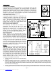
NTERNAL WIRING CONNECTIONS FOR THE CAS UNIT
Refer to Figure 3 for the internal wiring of the CAS-6/7 unit.
E
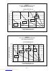
XTERNAL WIRING CONNECTIONS
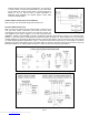
Refer to Figure 4 for typical 120 VAC oil fired burner or Figure 5 for 24
VAC gas fired burner connections that should be used when
connecting the CAS unit. Refer to Figure 6 for connecting a single 120
VAC appliance to the CAS, or Figure 7 for 24 VAC. The three wires
“BURNER”, “WHITE”, and “ORANGE” in Figure 4 correspond to the same wires shown in Figures 6 & 10. The three wires
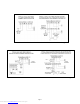
labeled 1, 2, and 3 in Figure 5 correspond to the same wires shown in Figures 7-9. Refer to Figures 8-10 for connecting
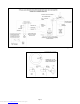
multiple appliances to one CAS unit. Note that an RJR-5 or RJR-6 relay and/or a CAC-24, CAC-120 or DIP-1 are required
on certain multiple-appliance applications. Figure 11 shows how the pressure switch port on the CAC/DIP-1 should be
attached to the CAS. Note that the correct 1/4" plastic tubing on the top of the CAS unit must be cut and a 3-way male
barb TEE suitable for 1/4" tubing installed as shown in order to connect the CAC pressure port/DIP-1.
Figure 4
Figure 5
Figure 6
Page 6
Downloaded from www.Manualslib.com manuals search engine