
User Guide

Page 2
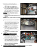
I. MOUNTING THE CONTROL BOX (Figure 1)
1. Remove the kit from the packaging and inspect for
shipping damage.
2. Place the pre-wired control box/thermal safety
switch assembly on top of the water heater.
3. Select a location for mounting the control box, so
that the water heater’s damper cable will reach the
socket provided inside the control box, and the
control box damper cable will reach the damper
motor. NOTE: The pressure switch on the control
box must be mounted vertically, see the warning on
the pressure switch.
WARNING:
DO NOT OBSCURE ANY EXISTING
WARNINGS OR OTHER IMPORTANT LABLES ON
THE WATER HEATER!
4. Mount the control box onto the water heater in the
location selected, using installer-supplied sheet metal screws though the four dimpled holes in the base of the
control box.
WARNING: DO NOT INSTALL SCREWS INTO A RACEWAY OR OTHER ENCLOSURE CONTAINING WIRING OR
ELECTRICALLY LIVE PARTS!
II. MOUNT THE THERMAL SAFETY SWITCHES (Figure
2)
1. Select locations for the two pre-wired thermal safety
switches on the draft hood. The thermal safety
switches should be mounted at right angles to each
other, and on the side of the draft hood that is
nearest to any potential source of depressurization
of the structure (vent fans, oven hoods etc.).
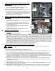
2. Mark the locations of the thermal safety switches,
and drill holes for the #10-24 mounting screws
provided.
3. Mount the switches onto the draft hood using the
screws, flat and serrated washers, and nuts
provided. Adjust the position of each switch such
that the edges of the sensors are 1/8” from the edge
of the draft hood.
4. Secure any excess cable with the cable clamps
provided.
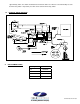
III. CONNECT TO APPLIANCE CONTROL AND
DAMPER (Figure 3)
3. Disconnect power to the water heater.
4. Remove a knockout from the control box for the
water heater damper cable, and install the supplied
plastic bushing into the knockout as shown.
5. Insert the water heater damper cable into the
control box through the bushing, and plug it into the
socket provided in the control box. BE SURE TO
ALIGN THE GROOVE IN THE PLUG WITH THE
SPLINE IN THE SOCKET WHEN INSERTING!
6. Connect the control box damper cable to the
automatic damper. BE SURE TO ALIGN THE
GROOVE IN THE PLUG WITH THE SPLINE IN
THE SOCKET WHEN INSERTING!
IV. INSTALL THE DI CONTROL KIT ADAPTER KIT ON THE DRAFT INDUCER
(Pressure sensing port)
1. Refer to the included instructions with the kit for this procedure.
Figure 2
Figure 3
Figure 1