
User Guide

Page 3
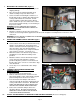
V. INSTALL THE DI-SERIES DRAFT INDUCER ON THE VENT
PIPE (Figure 4)
1. Refer to the included DI instruction manual for this
procedure. Set the draft adjustment plate on the draft
inducer to maximum setting before installing
NOTE: The draft inducer proving switch (DIP-1) is not required;
a proving switch is provided on the control box.
2. Connect the DI pressure sensing port as installed under step
IV to the pressure switch mounted on the control box, using
the supplied ¼” aluminum tubing and the supplied white
plastic nut on the pressure switch port.
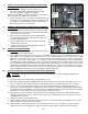
VI. CONNECT DRAFT INDUCER POWER CABLE TO CONTROL
BOX (Figure 5)
1. Remove a knockout from the control box, and connect the
conduit connector on the end of the draft inducer pre-wired
power cable to the control box.
2. Connect the green ground wire from the draft inducer to
the stripped green ground wire riveted to the control box,
using the supplied wire nut.
3. Connect the black wire from the draft inducer to the “M”
terminal on the control box.
4. Connect the white wire from the draft inducer to the “N”
terminal on the control box.
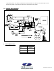
VII. CONNECT TO POWER SOURCE:
1. CAUTION:
Disconnect power to the intended power source
for the control box and draft inducer.
2. If local wiring codes allow, plug the 115V power cord from the control box into a 115V outlet having at least a 15
Amp Rating. If local wiring codes require that the unit be permanently wired into a power source, follow
guidelines to connect the power source to the L1(hot) and N (neutral) terminals on the control box and ground.
Wire the venter motor and controls in accordance with the National Electrical Code, manufacturer's
recommendations and/or applicable local codes. Units must be grounded. Check ground circuit to make certain
that the unit has been properly grounded. The wiring should be protected by an overcurrent circuit device rated at
15 amperes. CAUTION must be taken to ensure that the wiring does not come into contact with any heat source.
All line voltage and safety control circuits, between the venter and the appliance, must be wired in accordance
with the National Electrical Code for class one wiring or equivalent methods.
VIII. SET PRESSURE SWITCH AND PERFORM CHECK-OUT PROCEDURE:
WARNING
: The adjustment screw on the pressure switch MUST be set before putting the appliance into
service.
1. Reconnect power to the water heater and control box source(s).
2. Disable all ventilation and other equipment that may affect the air pressure in the area of the water heater, and
open a nearby door or window if possible, to ensure that the air pressure in the water heater area is neutral.
3. Create a call for heat from the water heater if necessary, by running hot water or temporarily resetting the
thermostat. The automatic damper should begin opening, and after a short delay, the draft inducer should begin
running and the burner should fire. If the burner does not fire with the damper open and the draft inducer running,
turn the pressure switch adjusting screw counterclockwise until the burner fires.
4. Allow burner to operate 5 minutes, then while the burner is still firing turn the pressure switch adjusting screw
clockwise until the burner shuts off. Now, back the screw out just until the burner fires, then back the screw out
an additional 1/8 to 1/4 turn.
5. Tighten the locknut on the adjusting screw.
6. While the burner is firing, disconnect power to the control box. The burner should shut off within a few seconds,
after the draft inducer motor shaft stops turning.
7. While the burner is firing, hold a match or other low-temperature heat source (do NOT use a propane torch or
similar device) up to the sensing disk on either of the thermal safety switches. When the disk is heated to
Figure 5
Figure 4
Pressure
Sensing
Port
White
Plastic
N
ut
Adjusting
Screw