
User Guide


Page 3
ADJUSTMENTS
P
ROVING SWITCH ADJUSTMENTS
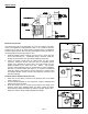
After proper air flow is established, the pressure switch adjustment is made by
turning the pressure switch adjustment screw clockwise (See Figure 4) until
burner operation stops. Turn the adjustment screw counterclockwise until
burner ignites. Turn the adjustment screw an additional 1/4 to 3/4 turn
counterclockwise to ensure adequate switch adjustment.
WARNING: Failure to properly adjust the pressure switch as specified above
could lead to improper operation of the pressure switch which will result in a
hazardous condition and bodily harm!
T
HERMOSTAT HEAT ANTICIPATOR ADJUSTMENT
After venting kit installation and checkout, check the amperage current draw through the
thermostat circuit and adjust the thermostat anticipator accordingly.
INSTALLATION OF GAS PRESSURE SWITCH
CAUTION: Check gas control valve pressure. Pressure MUST NOT exceed 14" WC
pressure.
1. Remove pressure tap plug in gas valve. (See Figure 5) NOTE: If installing on an
existing appliance, shut off gas supply to gas valve before plug removal.
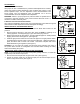
2. Replace the pressure tap plug with the 1/8" pipe nipple and pipe tee. Install pressure
tap plug at the bottom of the pipe tee. (See Figure 6)
3. Install the gas pressure switch into the side of the pipe tee. The gas pressure switch
is supplied with a restrictor orifice in the inlet and outlet ports. With these orifices in
place, the switch does not need to be vented. This feature complies with current
ANSI standards for gas regulators. (See Figure 7).
CAUTION: If for any reason the system has shut down during operation, the cause of
the system failure should be investigated and corrected before resetting the safety
switch and restarting the system.
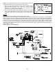
DRAFT HOOD SAFETY SWITCH INSTALLATION PROCEDURE
NOTE: 12 ga. wire should be used when wiring safety spillage switches, to reduce the
voltage drop in the thermocouple circuit.
1. Remove the thermocouple from the gas control valve. (See Figure 5)
2. Thread the junction block into the thermocouple port and thermocouple into the
bottom of the junction block. (See Figure 8)
Figure 4
Figure 5
Figure 6
Figure 7
Figure 8