
User Guide


Page 4
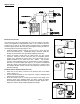
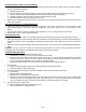
NOTE: Draft spillage switches should be mounted 90 degrees apart, and
mounted opposite from the vent outlet direction. (See Figure 9)
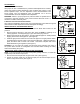
3. Mount the two spillage switches onto the draft hood and connect
inside terminals of switches with jumper wire. Connect outside
terminals to 6’ 12ga lead wires which are connected to the
thermocouple junction block. (See Diagram A)
4. Route jacketed lead wires or accepted wiring enclosure on the outside
of the water heater enclosure. Secure them to the enclosure with an
accepted hold down tab. Keep wiring away from any HOT surface
area.
WIRING
CAUTION: Disconnect electrical power when wiring power venter.
Wire the venter motor and controls in accordance with the National Electrical Code, manufacturer's recommendations
and/or applicable local codes. UNITS MUST BE GROUNDED. Check ground circuit to make certain that the unit has been
properly grounded. The wiring should be protected by an overcurrent circuit device rated at 15 amperes. CAUTION must
be taken to ensure that the wiring does not come into contact with any heat source. All line voltage and safety control
circuits, between the venter and the appliance, MUST be wired in accordance with the National Electrical Code for class
one wiring or equivalent methods. Route the venter motor and control wiring with an appropriate wiring method. Refer to
Wiring Diagrams A and B.
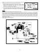
I
NTERNAL WIRING FOR CK-CONTROL KIT
Figure 9
Diagram A