
User Guide


Page 5
L1 to 1 on post purge timer T2 to timer relay base
M to 3 on post purge timer T3 to N/O on pressure switch
T1 to common on pressure switch Timer base to common on pressure switch
LOW VOLTAGE WIRING INSTRUCTIONS FOR
BOILERS:
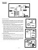
1. Route the appliance’s vent damper cable to
the CK-92*. Plug the cable into the
receptacle located inside the CK-92* using
the supplied plastic knockout grommet (if the
cable does not have a conduit connector).
(See Diagram A)
2. Connect the CK-92*’s pre-wired damper
cable to the vent damper (See Diagram A).
Snap the end of the flexible conduit into
place on the vent damper conduit bracket. If
the damper has a round type motor
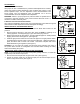
assembly and does not have a conduit bracket (See Diagram A), install the supplied
conduit bracket using the supplied #6 screws and nuts (See Figure 10). If it has a
rectangular or “box-like” motor assembly, refer to Fig. 11 for cable attachments.
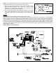
L
INE VOLTAGE WIRING INSTRUCTIONS
1. Connect 120 volts hot power source wire to terminal L1 on CK-92*.
2. Connect 120 volts neutral power source wire and white wire from venter motor to terminal N on the CK-92*.
3. Connect black wire from venter motor to terminal M on the CK-92*.
4. Wire gas pressure switch terminals COM and NO to L1 and M respectively, per local and national electrical code
requirements.
Refer to the SWG Venter installation instructions for setting system airflow.
Diagram B
Figure 11
Figure 10