
User Guide

Page 4
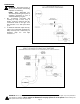
Figure 6
8. Attach the UV-Aire mounting base onto the plenum with the supplied sheet
metal screws. (Refer to template as shown in Figure 3) This must be tight in
order to activate the built in safety switch.
NOTE: DO NOT remove template from duct.
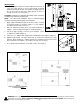
9. Do not handle the lamp with bare hands. Oils on your hands tend to reduce
lamp intensity. Install lamp into ballast. (See Figure 6)
10. Wipe off the lamp glass with the supplied alcohol wipe. Then insert the lamp
through the center hole of the mounting base. (See Figure 7) The power cord
must be 90° to the viewport hole on the mounting base.
11. With the ballast pressed against the mounting base, rotate the ballast clockwise
90°.
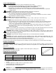
12. Do not wire the unit into the appliances 24 volt fan or thermostat circuit.
Premature failure of the ballast and lamp will occur. The warranty will be void.
Do not wire into a standard 120VAC electric supply. Wire according to Diagram
A or Diagram B. Unit is designed to be wired to a 24V/40VA power supply only.
Check lamp operation by looking through the viewport hole.
NOTE: The viewport hole is made of glass and will not allow any UVC rays to pass
through. A blue glow should be seen in the duct.
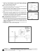
13. If blue glow is not seen, make sure the base is properly installed onto duct.
There is a proving switch located on the base that needs to be seated properly
onto the duct. Make sure when installing the base the plated washer on the
switch is raised approximately 3/16”. The proving switch must be fully
engaged. (See Figure 8)
14. With aluminum or foil tape, seal all joints and seams of the plenum near the
mounting location to reduce any direct viewing of light.
WARNING: Never expose eyes or skin to UVC light from any source. Looking directly at the UVC light may cause permanen
t
eye damage or blindness. Never operate the UV-Aire Air Purifying System out of the plenum. Avoid touching the
glass portion of the lamp with your hands.
Figure 7
Figure 8