
Submittal Sheet

Page 2
INSTALLATION AND ADJUSTMENT
NOTE: See sections on control locations and collar installation.
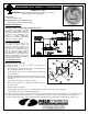
Insert the draft control into the collar. The front face of the control must be plumb. The pivot points
must be level whether the control is on a horizontal, vertical, or sloping flue pipe. Use a spirit level,
plumb and level accurately. Secure the control in the collar by tightening the clamping screws. If the
collar is not supplied by Field, the control may be held in place by small bolts or sheet metal screws
so located as not to interfere with the movement of the gate. When a sheet metal TEE is used
instead of the collar, the B dimension must not be less than indicated for proper operation. The “B”
dimension prevents the damper gate from obstructing the flue passage way.
See Figure 2 and Table 1.
VERTICAL FLUES
The control is shipped for installation in a vertical flue. The adjustment weight
should be in the right hand slot when you face the control. (See Figure 3)
HORIZONTAL FLUES
For horizontal flues, remove the weight from the right hand slot and attach it to
the left hand slot as shown in Figure 3.
ADJUSTING THE CONTROL
The burner must be running when the adjustment of the control is made. The
use of a draft gauge is required to accurately set the over fire draft. Set the
over fire draft according to the appliance manufactures installation instructions.
Set the control to maintain as low a draft as will give good combustion and
meet the requirements for heat. Turn the adjustment weight counter-clockwise
to loosen, then slide in slot to the proper position and tighten. The bracket is marked 2,4,6 and 8, which indicates draft settings of
.02”,.04”, etc. (These are drafts in flue adjacent to control, NOT over-fire drafts)
OIL BURNER COMBUSTION AIR AND OVERFIRE DRAFT SETTING (INCHES OF W.C.)
After the burner has operated for at least 5 to 10 minutes, take draft readings over the fire. For a domestic oil burner, the over-fire draft
should be approximately .02” to .03”, although there are some makes of burners which require higher drafts. Follow the burner
manufacturer installation instructions for proper settings. There must always be enough draft so that the burner does not puff back into
the room at the moment it starts, and there should be no objectionable smoke. CO
2
and smoke readings must be taken to determine
the proper adjustments.
ADDITIONAL APPLICATIONS (FOR RC SERIES DRAFT CONTROLS)
STOKERS
Adjustments must be made while the stoker is running, with a normal fuel bed depth and its fan adjusted to approximately the correct
setting.
A draft gauge must be used to accurately set the overfire draft. Follow the manufacture installation instructions for proper settings. If no
instructions are available.
For a domestic stoker, the draft should be set at -.04” OVER THE FIRE, with the STOKER ON. Have just enough draft so that at the
moment the stoker starts, it does not gas or puff back into the room through cracks around the fire door (with the fire door closed). If
there is objectionable smoke, increase draft slightly.
HAND FIRED PLANTS
Adjust the draft control when a good fire is burning. Close any check damper and open wide any internal damper.
Usually a draft of -.06” will be sufficient for cold weather, with reasonably quick pickup after a banked period. But if plant overheats,
change to a lower draft setting. Raise the setting if there is not enough heat.
In mild weather when less heat is needed, or the fire is to be banked, close ash pit draft door partly or entirely. If desired, a check
damper also can be used when banking the fire.
Figure 3
Table 1
RC SIZE B-DIMENSION
4 2 1/2 in.
5 2 1/2 in.
6 1 7/8 in.
7 2 5/8 in.
PN 02702600 Rev A 10/00