
Cascade Series Install Manual


page 10 of 16
INSTALLATION: WIRING & CONTROLS
The Cascade PSC Series Whole-House Fan Systems require a 115 volt electrical power supply of minimum 15A
The Cascade PSC Series Whole-House Fan Systems require a 115 volt electrical power supply of minimum 15A
ampacity and maximum 15 Amp circuit overcurrent protection.
ampacity and maximum 15 Amp circuit overcurrent protection.
All electrical components, whether included with the Cascade system or supplied by others, must be rated
All electrical components, whether included with the Cascade system or supplied by others, must be rated
for the fan system’s electrical load requirements; please refer to the Cascade Series speci cations table for the
for the fan system’s electrical load requirements; please refer to the Cascade Series speci cations table for the
electrical load requirements of the speci c model to be installed.
electrical load requirements of the speci c model to be installed.
All wiring and connections must be made according to this manual and all applicable electrical wiring
All wiring and connections must be made according to this manual and all applicable electrical wiring
codes and standards. All applicable electrical codes must be followed to the satisfaction of the local
codes and standards. All applicable electrical codes must be followed to the satisfaction of the local
authority having jurisdiction.
authority having jurisdiction.
A dedicated circuit is strongly recommended for this fan system.
A dedicated circuit is strongly recommended for this fan system.
P/N 780105001 11/20 Rev A
1. In the living space, install the single gang plastic outlet box (provided) in the desired location.
2. Run a 15-amp 115 VAC power circuit to the plastic outlet box installed in the living space using
romex 14-2 with ground wire (minimum). Refer to minimum ampacity and maximum overload
protection requirements listed for this power run. Note: a dedicated circuit is recommended.
Note: Romex wire is de ned as “wire Gauge - # of conductors” (ie: 14-2, 14-3). Always use Romex wire with
Ground or equivalent wire to meet branch circuit ampacity.
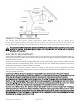
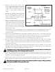
3. For CA2-CA5 models WHF installation using power cord supplied with fan (reference Diagram: 1), pull
14-2 romex wire (minimum wire size) from the single gang box to separate single-gang outlet
box installed in the attic less than 10 feet away from the fan assembly. The single-gang outlet box will
require a NEMA5-15R receptacle and cover plate. The romex wire, single-gang outlet box, NEMA5-
15R receptacle and cover plate are not supplied with product. Wall switch will allow fan to operate in
single speed operation.
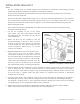
For CA2-CA5 models WHF installation hardwired (reference Diagram: 2), pull 14-3 romex wire (minimum
wire size) from the single gang plastic box directly to the fan assembly electrical box and remove the
fan power cord. Wall switch will allow fan to operate in two speed operation.
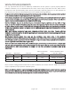
4. Make the wiring connections to the included switch as shown in Diagrams 1 and 2 for the fan model,
control kit provided and desired method of wiring (power cord or hardwired).
5. Install the switch into the outlet box, and install the included wall plate.
6. In the attic, make the wiring connections as shown in the appropriate wiring diagram in the fan
assembly handy-box or boxes.
7. Verify that grounding continuity is maintained properly to the fan assembly housing or housings.
8. Re-install the handy-box cover or covers.