
Submittal Sheet


Page 2
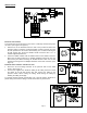
INSTALLATION
MOUNTING JUNCTION BOX
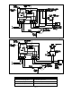
The junction box can be mounted at the venter or remotely mounted away from
the venter. (See Figure 1 & Figure 2)
1. Remove one of the knockouts from the side of the junction box where the
pressure switch is mounted. Install the flexible conduit connector onto the
CK-43F junction box and secure with fastening nut. If remote mounting the
CK-43F junction box, mount the flexible conduit connector onto a 2" x 4"
installer supplied junction box.
2. Fasten the flexible conduit from the SWG Venter into the conduit connector.
Mount the CK-43F junction box or installer supplied junction box onto the
wall or floor joist without straining the flexible conduit. Fasten the CK-43F
junction box through the four dimpled locations on the base of the box. (See
Figure 3)
PRESSURE SWITCH SENSING TUBE INSTALLATION
1. Attach the 1/4 inch tubing connector to the pressure tube on the SWG
Venter. (See Figure 3)
2. Connect the supplied 1/4" aluminum tubing to the tubing connector. Route
the tubing to the CK-43F junction box and connect the tubing to the
pressure switch. When routing the tubing, avoid kinking the tubing by
bending the tubing too sharply.
For remote mounted CK-43F Junction Box, use a 1/4" OD copper, aluminum or
plastic tubing and route the tubing to avoid contact with any heat source.
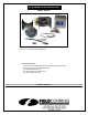
Typical Vent System Layout
Figure 1
Figure 2
Figure 3