
Submittal Sheet


Page 3
DRAFT CONTROL INSTALLATION
CAUTION: This draft control is shipped as a single acting draft control. If the draft
control is not being used on a gas draft induced furnace, remove the gate stop on
the draft control ring before installing.
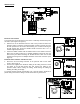
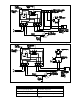
COLLAR INSTALLATION
This control is shipped with a collar patterned to fit a single wall round vent pipe. To
attach this collar to the flue, see Figure 4 and follow the instructions below.
1. Bend outward the two ears at the front corners of the collar. Bend 90 degrees,
1/4 inch behind the single hole on the straps.
2. Insert clamping screw in ears on collar and bolt the remainder of the collar
together.
3. Hold the collar against the side of the flue in the exact position it is to be installed (shown by dotted lines) and mark
the outline of the collar on the flue.
4. Cut a hole in the flue about 1/2" inside of this outline.
5. Make a series of cuts about 1/2" apart from the edge of this hole to the outline marks.
6. Strap the collar to the flue pipe.
7. Bend the tabs formed by the series of cuts outward against the inside of the collar to make a tight joint.
8. Insert the draft control. (See Draft Control Installation and Adjustment Section.)
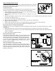
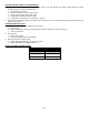
DRAFT CONTROL INSTALLATION IN TYPE B VENT PIPE
CAUTION: DO NOT use the supplied collar when mounting draft control to Type B Vent Pipe. Install by using a Type B
Vent Pipe Tee.
1. Install a vent pipe reducer or increaser into the inner pipe and fasten using sheet metal screws. (See Figure 5)
2. The opening of the Type B Vent Tee, at the draft control mounting location, should be sealed with a high temperature
sealant or equivalent.
3. Refer to Draft Control Installation Section.
DRAFT CONTROL INSTALLATION
Insert the draft control into the collar or tee. The front face of the
control MUST be plumb and the bearing surfaces MUST be level
whether the control is on a horizontal, vertical or sloping flue pipe.
Use a spirit level and level accurately. (See Figure 5) Secure the
control in the collar by tightening the clamping screws. If a tee is
used or a collar is supplied locally, the control may be held in
place by sheet metal screws.
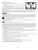
ADJUSTING THE DRAFT CONTROL WITH 4" MG1
The control MUST be adjusted to the desired draft setting by
adding or removing the washer-type weights supported by the two
chains on the side of the draft control. (See Figure 6) DO NOT
move the weight attached directly to the gate, this is used only for
balancing at the factory.
Figure 5
Figure 6
Figure 4