
Submittal Sheet
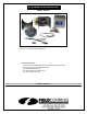


Page 4
WHAT DRAFT SETTING TO USE
When adjusting the control, two things are essential:
1. The burner must be operating for at least 10 minutes to obtain maximum
chimney draft.
2. An analysis of the flue gases is necessary to determine the percentage of
CO
2
and check for presence of CO.
Refer to the appliance instructions and/or to the local gas company for the proper
CO
2
readings and allowable CO levels. A rule of thumb for draft setting is
between .01" to .03" of water column draft at the appliance outlet. (Check
equipment requirement.)
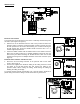
Changes in the adjustment of the 4" MG1 control should be made by adding or removing the washer-like weights
(supplied with the control) to or from the weight holder chain assembly. After the control is adjusted, it's action will be
entirely automatic, the gate will open or close by itself to correct for changes in the draft that occur in the chimney.
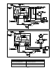
ADJUSTMENTS
PROVING SWITCH ADJUSTMENTS
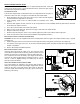
After proper airflow is established, the pressure switch adjustment is made by turning the pressure switch adjustment
screw clockwise (See Figure 7) until burner operation stops. Turn the adjustment screw counterclockwise until burner
ignites. Turn the adjustment screw an additional 1/4 to 3/4 turn counterclockwise to ensure adequate switch adjustment.
WARNING: Failure to properly adjust the pressure switch as specified above could lead to improper operation of
the pressure switch which will result in a hazardous condition and bodily harm!
THERMOSTAT HEAT ANTICIPATOR ADJUSTMENT
After venting kit installation and checkout, check the amperage current draw through the thermostat circuit and adjust the
thermostat anticipator accordingly.
WIRING
CAUTION: Disconnect electrical power when wiring power venter.
Wire the venter motor and controls in accordance with the National Electrical Code, manufacturer's recommendations
and/or applicable local codes. UNITS MUST BE GROUNDED. Check ground circuit to make certain that the unit has been
properly grounded. The wiring should be protected by an overcurrent circuit device rated at 15 amperes. CAUTION must
be taken to ensure that the wiring does not come into contact with any heat source. All line voltage and safety control
circuits, between the venter and the appliance, MUST be wired in accordance with the National Electrical Code for class
one wiring or equivalent methods. Route the venter motor and control wiring with an appropriate wiring method. Refer to
Wiring Diagrams A and B.
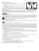
LOW VOLTAGE WIRING INSTRUCTIONS FOR BOILERS AND WARM AIR FURNACES
1. With boilers, locate terminal on spark ignition module or gas valve (if standing pilot) which would normally be 24 volts
hot on a call for heat. With spark ignition systems, this terminal could be TH-W, 24 V, THS or T1 depending on the
spark ignition control.
2. With warm air furnaces, locate terminal W in furnace junction box.
3. Remove wire from this terminal and reroute to T1 on CK-43F.
4. With boilers, connect T3 on CK-43F to hot side of gas valve (if standing pilot) or to terminal TH-W, 24 V, THS or T1 if
spark ignition.
NOTE: Remember, the correct terminal is the one that would normally be hot on a call for heat.
5. With warm air furnaces, connect T3 on CK-43F to terminal W in furnace junction box.
6. Connect T2 on CK-43F to a 24 volt neutral where convenient.
LINE VOLTAGE WIRING INSTRUCTIONS
1. Connect 120 volts hot power source wire to terminal L1 on CK-43F.
2. Connect 120 volts neutral power source wire and white wire from venter motor to terminal N on the CK-43F.
3. Connect black wire from venter motor to terminal M on the CK-43F.
Refer to the SWG Venter installation instructions for setting system airflow.
Figure 7