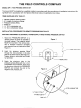
. THE FIELD CONTROLS COMPANY MODEL DIP-1: FAN PROVING SWITCH KIT This device MUST be installed by a qualified installer in accordance with the manufacturer's installation instructions. Wiring MUST be in accordance with the National Electrical Code and applicable local codes. ITEMS SUPPLIED WITH THIS KIT: 1 Remote pressure sensing switch 1§ ft. length of aluminum tubing 1 Pressure sensing fitting 1 Brass nut 1-%" 0.D. compression nut 1-1" O.
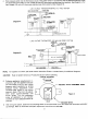
4. Wire pressure switch into the thermostat circuit of the power center in accordance with the National Electrical Code and applicable local codes. For tow voltage (24 volts AC) thermostat operated gas fired systems, See Diagram A. For high voltage (120 volts AC) thermostat operated gas fired systems, (See Diagram B).
ADJUSTING THERMOSTAT ANTICIPATORY: Disconnect one side of the thermostat circuit at the gas naive or burner control, and connect an ampere meter in the circuit. With the system running, take an amperage reading on the circuit. Check the nameplate or instructions for the thermostat to obtain the proper amperage level. Adjunct amperage level by moving the anticipatory lever. Reconnect the thermostat to the gas valve and start the system operating.