Operation and Installation Manual FC95HRV* FC155HRV FC200HRV* FC150ERV Heat Recovery Ventilators * This product earned the ENERGY STAR by meeting strict energy efficiency guidelines set by Natural Resources Canada and the US EPA. It meets ENERGY STAR requirements only when used in Canada.
CAUTION Table of Contents Getting to Know your Heat and Energy Recovery Ventilator Ventilation and Control Options How the Dehumidistat Works (Colder Climates) Glossary and Additional Information Warranty........................................................................................3 Healthy Home System™ Control (HHSC) Dehumidistat .................................................................................4 Dehumidistat Ventilation Control .................................................
Getting to Know your Heat and Energy Recovery Ventilator (FC Series) • Recovers the majority of the energy contained in the exhausted stale air. • Uses the recovered energy to preheat or precool the fresh outdoor air introduced into the house • Distributes the fresh air throughout your home. Thank you for purchasing a Field Control Heat/Energy Recovery Ventilator (HRV/ERV). The HRV/ERV provides fresh air to your home while recovering energy from the air it exhausts.
Healthy Home System Control (HHSC) The Healthy Home System Control (HHSC) activates the HRV/ERV automatically to deliver fresh air into your home. Setting the Control The duration of the ventilation rate is adjustable on the HHSC. Your installer sets up this control during the installation of your system . Refer to the instructions that came with the HHSC for the setup information.
The Dehumidistat Ventilation Control Part #DHVC The Dehumidistat Ventilation Control offers ON/OFF, High Speed/Low speed plus an electronic dehumidistat. Instruction card Key Features • 2 Speed Fan setting (Low/High) • Electronic Dehumidistat • Instruction Card is inserted in the control On indicator light • Slim-line design • Connect to 3 wire 20 gauge low voltage wire.
Optional Vent Timer Control (VTC) The timer will override the Operational Mode (regardless of the setting) and initiate high speed ventilation. Upon completion of the timer cycle, the HRV/ERV returns to your selected Operational Mode and speed setting. ATTENTION If the system does not have a main control installed, the HRV/ERV Terminal Block must have a jumper installed between 2 (ON) and 3 (RED). Refer to “Operating the HRV/ERV without a Main Control” in this manual.
Maintenance Routine for HRV 1. Inspect Exterior Hoods at least once a month. 6. Clean Duct Work if Required The duct work running to and from the HRV may accumulate dirt. Wipe and vacuum the duct once every year. You may wish to contact a Heating/Ventilation company to do this. WARNING: Blockage of hoods may cause an imbalance. 7. General Maintenance - Twice a Year Make sure exhaust and fresh air supply hoods are not blocked or restricted by leaves, grass, or snow.
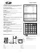
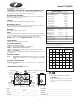
Model FC95HRV Performance (HVI certified) THERMALLY CONDUCTIVE, PATENTED ALUMINUM CORE The cross-flow heat recovery core transfers heat between the two airstreams. It is easily removed for cleaning or service. Net supply air flow in cfm (L/s) against external static pressure E.S.P (external static pressure) MOTORS AND BLOWERS Each air stream has one centrifugal blower driven by a common PSC motor. The unit has a 2 speed fan operation. FILTERS Washable air filters in exhaust and supply air streams.
Port Configuration and Airflow Model FC95HRV In order to make the HRV as space efficient as possible, the INDOOR supply and return ports are converted from round to oval shape. Overall size of the port remains the same. Simply bend a standard duct fitting to the correct shape, and attach to the oval port using the same method as for a round port. Round port bent to oval FC95HRV Air Flow Stale air enters the FRONT-RIGHT side port.
Model FC155HRV THERMALLY CONDUCTIVE, PATENTED ALUMINUM CORE The cross-flow heat recovery core transfers heat between the two airstreams. It is easily removed for cleaning or service. MOTORS AND BLOWERS Each air stream has one centrifugal blower driven by a common PSC motor. 2 speed fan operation. Performance (HVI certified) Net supply air flow in cfm (L/s) against external static pressure E.S.P (external static pressure) FILTERS Washable air filters in exhaust and supply air streams.
Model FC200HRV THERMALLY CONDUCTIVE, PATENTED ALUMINUM CORE The cross-flow heat recovery core transfers heat between the two airstreams. It is easily removed for cleaning or service. Performance (HVI certified) Net supply air flow in cfm (L/s) against external static pressure E.S.P (external static pressure) MOTORS AND BLOWERS Each air stream has one centrifugal blower driven by a common PSC motor. 2 speed fan operation. FILTERS Washable air filters in exhaust and supply air streams.
Model FC150ERV LATENT RECOVERY/MOISTURE TRANSFER CORE The cross-flow energy recovery core transfers heat and water vapor between the two airstreams. It is easily removed for cleaning or service. MOTORS AND BLOWERS Each air stream has one centrifugal blower driven by a common PSC motor. 5 speed fan operation. FILTERS Washable air filters in exhaust and supply air streams. MOUNTING THE ERV Four threaded inserts at corners of case designed to accept the "S" hooks and hanging straps supplied with the unit.
Installation Methods The Three Methods of Installation The following three installation methods are for the HRV/ERV system: • The Simplified installation. • The Partially Dedicated Installation • The Fully Dedicated Installation Installing the Ducting Between the HRV/ERV & Living Areas in the House A well designed and installed ducting system will allow the HRV/ERV to operate at its maximum efficiency. All ducts should be kept short and have as few bends or elbows as possible to maximize airflow.
Simplified Installation Diagrams Simplified Installation (Return/Return Method) Key Points • The HRV/ERV must be balanced. • It is mandatory that the furnace blower run continuously or HRV/ERV operation be interlocked with the furnace blower. (Refer to “Interlocking the HRV/ERV to an Air Handler/Furnace Blower.”) • The duct configuration may change depending on the HRV/ERV model. See specifications for your unit. • Check local codes / authority having jurisdiction for acceptance.
Partially Dedicated Installation Diagrams Partially Dedicated System This installation enables stale air to be drawn from the poorest air quality areas of the home (bathrooms, kitchen). Key Points • The HRV/ERV must be balanced. • It is recommended that the furnace blower run continuously or HRV/ERV operation be interlocked with the furnace blower to evenly distribute the fresh air throughout the house.(Refer to “Interlocking the HRV/ERV to an Air Handler/Furnace Blower.
Fully Dedicated Installation Diagrams Fully Dedicated System This is a stand alone HRV/ERV system which is not connected to a force air system. Stale air is drawn from key areas of the home (bathroom, kitchen) while fresh air is supplied to main living areas. Key Points • The HRV/ERV must be balanced. • The duct configuration may change depending on the HRV/ERV model. See specifications for your unit. • Check local codes / authority having jurisdiction for acceptance.
Installation Location Install the unit in a heated space that provides convenient space for service access. A typical location is in either a mechanical room or an area close to the outside wall within close proximity to where the weatherhoods are mounted. If a basement area is inconvenient or non- existent, install the unit in a utility or laundry room. WARNING Improper installation, adjustment, alteration, service or maintenance can cause property damage, personal injury or loss of life.
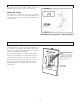
Drain Connection (HRV only) Drain Connection The HRV may produce some condensation during a defrost cycle. This water should flow into a nearby drain, or be taken away by a condensate pump. DRAIN HOSE PLUMBING PRE-PUNCHED HOLES (2) DRAIN PAN CAUTION DRAIN PAN DRAIN SPOUT The HRV and all condensate lines must be installed in a space where the temperature is maintained above the freezing point or freeze protection must be provided.
Weatherhood Installation Installing the Ducting from the Weatherhoods to the HRV/ERV Weatherhoods Fixed covered weatherhoods have a built-in bird screen with a 1/4" (6mm) mesh to prevent foreign objects from entering the ductwork. The inner and outer liners of the flexible insulated duct must be clamped to the sleeve of the weatherhoods (as close to the outside as possible) and the appropriate port on the HRV/ERV.
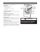
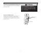
Installation of the Dehumidistat or Dehumidistat Ventilation Control Standard Series Controls may be installed onto a flush mounted 2" x 4" electrical switch box or it may be surface mounted onto a wall. ATTENTION Pay special attention not to damage the Contact Pins when attaching and detaching the Face Plate. (Figure B) Only 1 master control should be installed to a ventilation system (the Face Plate on this illustration may not be exactly the same as yours). 1.
Installation and Operation of 20/40/60 Minute Timer Operating your 20/40/60 Minute Timer Press and release the Select Button to activate high speed override. The High Speed Status Light will illuminate and the unit will run on high speed ventilation for 20 minutes. The 20/40/60 Minute timers provide an extended override time of 20 - 40 additional minutes simply by pressing and releasing the select button. High Speed Status Lights The High Speed Status Light will dim after 10 seconds of run time.
Installation of the Healthy Home System™ Control (HHSC) Choose a Location The HHSC controller can be installed anywhere in your home. To simplify the installation, locate the HHSC control near the HVAC system and/or the HRV/ERV, since the HHSC does not require routine adjustment or occupant interaction. To provide the occupants with direct access to the functions of the controls, install optional accessory controls throughout the house. How To Install the Controller 1.
Installation of the Healthy Home System™ Control (HHSC) HHSC CONTROL FACTORY-INSTALLED JUMPER DO NOT REMOVE 1 LO HI 6 2 ON C 7 3 R NO 8 4 Y NC 9 5 G BK 10 R C Wt Gt R Y W G Gf V LO HI * 24C HRV/ERV WIRING TERMINALS R C W Y FURNACE OR HEAT PUMP G THERMOSTAT 12V/24 VAC Field wiring, 20 AWG min. required * Connect V Terminal on the HHSC Control to the Hi Terminal (instead of Lo) for a shorter ventilation period.
Installation of the HHSC with the DH1 and 20/40/60 Minute Timers (test a) DH1 DEHUMIDISTAT (OPTIONAL)** % HHSC CONTROL 80 FACTORY-INSTALLED JUMPER DO NOT REMOVE 20 Y R G 1 LO HI 6 2 ON C 7 3 R NO 8 4 Y NC 9 5 G BK 10 R C Wt Gt R Y W G Gf V LO HI * 24C HRV/ERV WIRING TERMINALS Y Y R R G G R C W Y FURNACE OR HEAT PUMP G THERMOSTAT 12V/24 VAC Field wiring, 20 AWG min.
Installation of the DHVC Ventilation Control with 20/40/60 Minute Timers (test c) DHVC VENTILATION CONTROL % NOTE: These connections are not necessary if the system is configured as fully dedicated (no central HVAC connections). 80 HIGH 20 R Y FACTORY-INSTALLED JUMPER FOR STANDBY-OFF OPERATION.
Interlocking the HRV/ERV to an Air Handler/Furnace Blower Connecting the HRV/ERV as illustrated will ensure the Air Handler/Furnace Blower Motor is operating whenever the HRV/ERV is ventilating. CAUTION The HRV/ERV must be interlocked to the Furnace/Air Handler with a Simplified Installation (Return/Return Installation) and should be interlocked with a Partially Dedicated Installation.
Balancing the Air Flows Balancing the air flows is critical to ensuring that the amount of air introduced from the outside of the building equals the amount of air exhausted to the outside of the building.
Balancing the Air Flows with a Pitot Tube STEP 1. Drill a 3/16” hole in the duct (ideally 3 feet downstream of STEP 2. Insert the Pitot tube with the tip facing towards the air any elbows or bends and 1 foot upstream of any elbows or bends) in the Fresh Air and Stale air streams. stream in the Stale Air From Building air stream. Move the Pitot tube around in the duct (facing towards the airflow) and take an average reading. Record the reading.
Air Flow Balancing using the Door Ports Step 4 Door balancing ports (not on all models) are designed to be used in conjunction with a Magnehelic Gauge or Digital Manometer to Close the HRV Door. Initiate power and operate the HRV on high speed. Operate the forced air system on high speed (if the HRV is connected to the forced air system) . measure the Stale and Fresh airflows for balancing.
Balancing Dampers The FC155HRV and FC200HRV models have factory installed Balancing Dampers located in the “Fresh Air to Building” and “Stale Air from Building” collars. All other units require the installation of balancing dampers (not included) in the “Fresh Air to Building” and “Stale Air from Building” ductwork. Refer to the installation diagrams in this manual for the Simplified, Partially Dedicated, and Fully Dedicated systems.
Troubleshooting your HRV/ERV System SYMPTOM CAUSE SOLUTION Poor Air Flows • 1/4” (6 mm) mesh on the outside hoods is plugged • filters plugged • core obstructed • house grilles closed or blocked • dampers are closed if installed • poor power supply at site • ductwork is restricting HRV • improper speed control setting • HRV airflow improperly balanced • clean exterior hoods or vents • remove and clean filter • remove and clean core • check and open grilles • open and adjust dampers • have electrician
Residential Wiring Diagram Models FC95HRv, FC155HRV, FC200HRV, and FC150ERV Field Controls FC95HRV, FC155HRV, FC200HRV, FC150ERV LOW HI ON COM RED NO YEL NC GRN BLK LEGEND HIGH VOLTAGE NOTE: Jumper between 2 ON and 3 RED Thermistor (Not on all units) 12/24V LOW VOLTAGE P5 P4 BLUE P7 COMMS BLACK K2 P9 K7 K3 K4 GREEN P1 WHITE P3 T4 24COM LO VENT HI VENT AUTOTRANSFORMER BLACK NO NC NO COM COM 24VAC COIL A WHITE NC BROWN RED B K5 BLUE K6 SEE DEFROST DETAIL Note: