
Manual


Page 2
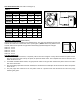
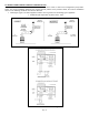
UNIT SPECIFICATIONS
(See Table 1 and Figure 1)
Table 1
UNIT DIMENSIONS (INCHES)
MODEL “H” “W” “D” I/O*
PVG-100
7.5 10.0 7.0 4/4
PVG-300
7.5 11.5 7.0 4/4
PVG-600
8.75 12.0 8.5 5/5
*
Inlet and outlet diameter.
ELECTRICAL RATINGS
MODEL VAC Hz RPM WATT AMP TP**
PVG-100
115 60 3000 145 2.1 YES
PVG-300
115 60 3000 145 2.1 YES
PVG-600
115 60 3000 167 1.5 YES
**
Thermally protected motor.
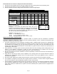
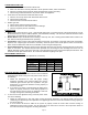
SIDEWALL VENT HOODS (Model SWH-1)
Sidewall vent hoods are available in the following sizes. The vent hood should be chosen that
matches the outlet size of the Power Venter. (See Figure 2) NOTE: When using different sizes
consider reducers and specific size pipe when determining equivalent length of vent pipe.
SWH-1-3 - 3 inch
SWH-1-4 - 4 inch
SWH-1-5 - 5 inch
SWH-1-6 - 6 inch
SWH-1-8 - 8 inch
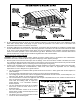
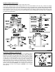
SYSTEM OPERATION
1. The thermostat (wall thermostat, or aquastat) calls for heat and energizes a relay which activates the power venter.
After the venter motor has come up to speed, the pressure switch closes. This completes the circuit to the burner and
allows the burner to fire.
2. For millivolt controlled water heaters, the gas pressure switch on the gas valve activates the power venter at the same
time as the burner fires.
3. After the heating requirement has been satisfied, the thermostat circuit will open and de-activate the burner and power
venter circuit.
4. The post purge timer continues to run the power venter for a period of time after the burner has shut off to purge
remaining flue gases.
Figure 2
Figure 1