
Manual


Page 7
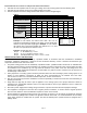
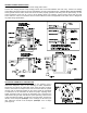
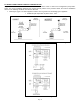
GENERAL WIRING INSTRUCTIONS
CAUTION: Disconnect electrical power before wiring power venter!
Connect line voltage (110/120 VAC) through junction box access hole labelled "120 VAC Only". Connect low voltage
control wiring through junction box access hole labelled "24 VAC Control Wiring Only". VENTER MUST BE GROUNDED!
Check ground circuit to make certain that venter has been properly grounded. The wiring must be protected by an over
current protection circuit such as a fuse or circuit breaker rated at 15 amperes. Prevent wiring contact with any heat
source. Wire the venter in accordance with the National Electrical Code and applicable local codes. Refer to Diagram B
for proper wiring specifications.
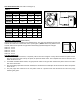
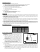
ADJUSTING THERMOSTAT ANTICIPATOR
If connecting the Power Venter system to a gas appliance with a
thermostat anticipator, refer to the following to make adjustments.
Disconnect one side of the thermostat circuit at the gas valve or burner
control, and connect an ampere meter into the circuit. With the system
running, take an amperage reading on the circuit. Check the nameplate
or instructions for the thermostat to obtain the proper amperage level.
Adjust amperage level by moving the anticipator lever. Reconnect the
thermostat to the gas valve and start the system operating. Time the burn
cycles and adjust as follows; To make the cycle time longer, increase the
amount on the anticipator (Example: .45 to .5 Amps); to decrease cycle
time, reduce the amount on the anticipator. (Example: .45 to .3 Amps)
(See Figure 8)
Diagram B
Figure 8