
Manual


Page 8
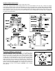
AIR FLOW ADJUSTMENTS
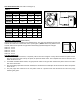
1. To properly adjust the venter air flow, loosen the inlet ring screws and open the choke plate approximately 1/2 to 3/4
open. (See Figure 10) Start the heating appliance following the manufacturer specified procedure, and set the
thermostat to call for heat.
2. After the system has operated for several minutes to stabilize the exhaust gas temperature, check for air flow at the
draft hood or the heating appliance outlet using a velocity meter, draft meter, or match test procedure.
3. Adjust the venter choke plate inward or outward to obtain the minimum draft necessary to maintain venting. Then
increase the draft slightly (Approximately 10% over minimum flow rate) to ensure proper venting during any variations
in venter performance, such as wind load or house depressurization.
4. Secure the choke plate into position by tightening the screws on the inlet collar (See Figure 9)
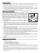
GENERAL INSTALLATION INSPECTION
Follow recommended procedures for safety inspection of a heating appliance in accordance with the National Fuel Gas
Code A.N.S.I. Z223.1. The following procedure will help in evaluation of the venting
system. It is intended as a guide to aid in determining that the appliance is properly
installed and is in a safe condition for continuous use. This is a generalized procedure
which cannot anticipate all situations. Accordingly, in some cases deviation from this
procedure may be necessary to determine safe operation of the equipment. If it is
determined that a condition which could result in unsafe operation exists, the appliance
should be shut off and the owner advised of the unsafe conditions. Corrections must be
made prior to allowing continuous operation. The following steps should be taken in
making a safety inspection.
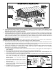
1. Visually inspect the venting system for proper size and determine that there is no
blockage, restriction, leakage, corrosion, or other deficiencies which could cause
unsafe operation.
2. To the extent possible, close all building doors, windows, and all doors to the room in which the heating appliance is
located. Turn on clothes dryers and any exhaust fans so that they operate at maximum speed. Do not operate a
summer exhaust fan. Also close all fireplace dampers. If after completing steps 3 through 7 it is believed that sufficient
combustion air is not available, refer to the National Fuel Gas Code A.N.S.I. Z223.1 or any local codes for proper
guidelines.
3. Place the appliance being inspected into operation. Follow the lighting instructions and adjust the thermostat so that
the heating appliance will operate continuously.
4. Determine that the burner is operating properly and that the main burner ignition functions satisfactorily, by
interrupting the electrical power of the appliance in any safely convenient manner. Test the burner safety device to
determine if it is operating properly by extinguishing the pilot or disconnecting the flame safety circuit.
5. Visually determine that the main burner is burning properly, i.e. no floating, lifting, or flashbacks. Adjust the primary air
shutter as required by the appliance manufacturer. If the appliance is equipped with high and low flame control or
flame modulation, check for proper main burner operation at both flame levels.
6. Test for exhaust gas spillage at the draft hood or the barometric draft control after approximately 5 minutes of main
burner operation. Use a draft meter or flame or smoke from match, candle or cigarette.
7. Turn on all fuel burning appliances within the same room so that they operate at their maximum capacity. Then repeat
Steps 5 and 6.
8. Return all doors, windows, exhaust fans, fireplace dampers, and any other fuel burning appliances to their previous
condition.
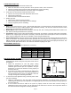
SYSTEM CONTROL CHECK PROCEDURES
1. Adjust the thermostat to call for heat and observe the power venting system for proper operation sequence. Repeat as
necessary.
a. Thermostat calls for heat.
b. Venter relay is energized which starts venter motor.
c. Pressure switch closes which allows burner to fire.
d. Thermostat is satisfied, burner stops operation.
e. Venter continues to operate for up to 2 minutes during the post purge cycle.
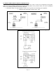
2. While the system is in operation, disconnect the draft tube from the air pressure switch. The pressure switch should
open and interrupt burner operation. Re-connect the draft tube to the air pressure switch which should allow the
burner re-light.
3. If a GSK-3 secondary safety switch is installed, allow the vent pipe to cool and disconnect the vent pipe between the
appliance outlet and venter inlet. Block the vent connected to the appliance with a non-combustible material. Activate
the heating system main burner and verify that the GSK-3 shuts down the burner within a few minutes or less. Reset
the GSK-3 and repeat.
Figure 9