
Manual


Page 9
TROUBLESHOOTING TIPS
1. Burner does not fire when thermostat calls for heat.
a. Make sure draft tube is securely fastened to the air pressure switch, and is not blocked.
b. Check for continuity across pressure switch terminals when venter is operating.
c. Check wiring connections between air pressure switch and appliance.
2. Venter does not activate when thermostat calls for heat.
a. Check to see if relay closes when thermostat calls for heat.
b. Check wiring connections.
c. Check motor for unrestricted shaft rotation.
3. Exhaust gas odor.
a. Check system draft level during operation.
b. Check vent system on outlet side of venter for leakage.
c. Check for negative pressure in building.
MAINTENANCE
1. Motor: Inspect the motor once a year - motor should rotate freely. To prolong the life of the PVG-600 motor, it must
be lubricated with six drops of SWG Superlube, Part #46226200, annually. The PVG-100 and PVG-300 have sealed
ball bearings, and therefore do not need to be oiled.
2. Blower Wheel: Inspect the blower wheel annually to clear any soot, ash or coating which inhibits either rotation or air
flow. Remove all foreign materials before operating.
3. Vent System: Inspect all vent connections annually for looseness, for evidence of corrosion and for flue gas leakage.
Replace, seal, or tighten pipe connections if necessary. Check the power venter choke plate to insure it is secured in
place. Check the barometric draft control, if installed, to insure the gate swings freely.
4. System Safety Devices: With the heating system operating disconnect the pressure sensing tube from the pressure
switch on the venter. This should stop the burner operation. Re-connecting the tube will relight the burner. For 30
millivolt operating systems, disconnect one lead of the spill switch circuit from the thermocouple junction block. This
should shut off the pilot and the burner. Re-connection will allow re-lighting of the pilot.
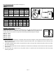
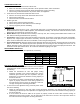
REPLACEMENT PARTS LIST
The following items are available for replacement, if necessary.
REPLACEMENT PARTS LIST
DESCRIPTION PV
G
-
100 PV
G
-
300 PV
G
-
600
Motor 46032000 46032000 46083300
Blower Wheel 46080100 46033400 46089400
24 VAC Rela
y
46282800 46282800 46282800
Pressure Switch 46282900 46246100 46283000
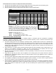
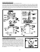
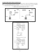
MULTIPLE VENTING SYSTEMS
1. To vent a 24 VAC controlled boiler or furnace and a 30 millivolt
residential water heater using one PVG power venter refer to
the following.
a. Follow the instructions for safe and proper venting
previously specified in this manual. Make sure that the
combined gross BTU/Hr input and equivalent vent pipe
length does not exceed the maximum venting capacity of
the venter selected.
b. A CK-20FV or CK-20FG control kit MUST be added to the
system to properly control the venter during operation of
the water heater. Refer to Figure 10, Diagram C and D for
vent pipe arrangement and wiring information.
2. To vent two 24 VAC appliances using one PVG power venter
refer to the following.
a. Follow the instructions for safe and proper venting previously specified in this manual. Make sure that the
combined gross BTU/Hr input and equivalent vent pipe length does not exceed the maximum venting capacity of
the venter selected.
b. A CK-41 Control Kit must be added to the system to properly control the venter when common venting an
additional 24 VAC furnace or boiler. Tee the draft tube on the PVG unit to connect to the air pressure switch on
the Control Kit. Refer to Diagram D for wiring instructions.
Figure 10