
Air Purifying Sstem Installation Guide

Page 8
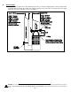
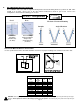
V. ALARM CIRCUIT WIRING
The UV Aire units supplied with a circuit board allows for the wiring of the UV Aire unit into an alarm or security system to
monitor the operation of the UV lamp. This circuit is a set of normal open contacts that close if the operational time
exceeds 9000 hrs or if the lamp burns out.
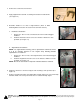
1. Turn off power switch on the UV Aire unit and unplug the unit before doing any wiring.
2. Loosen the cover screw and open the unit cover.
3. Locate terminals 1-2 on the circuit board and remove the jumper wire.
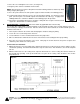
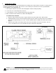
4. Wire to terminals A1-A2 and wire in accordance with Diagram B.
S
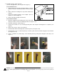
YSTEM CHECK OUT PROCEDURE
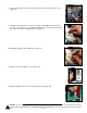
1. Plug the UV Aire back into the power receptacle and leave the power switch in the “OFF” position.
2. Unplug the Ballast connector from the lamp and switch the power switch to the ON position. The unit will start
and operate for approximately 10 seconds. Then the LED will switch to a RED color and the alarm contact
will close.
3. Switch the power switch to the OFF position and reconnect the ballast connection to the lamp. Close the
cover, secure with the cover screw, and switch the power switch to the ON position.
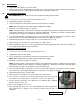
WARNING: Never expose eyes or skin to UVC light from any source. Looking directly at the UVC light may cause permanent eye damage o
r
blindness. Never operate the UV-Aire™ Air Purifying System out of the plenum. Avoid touching the glass portion of the lamp with you
r
hands.
Diagram B