Installation, Operation and Maintenance Manual Oil Fired Warm Air Furnaces WML-C AND MPL-B (Down-Flow or Horizontal Model) ALL INSTALLATIONS MUST MEET ALL LOCAL, PROVINCIAL/STATE, AND FEDERAL CODES WHICH MAY DIFFER FROM THIS MANUAL ECR International Limited OLSEN Division Read this complete manual before beginning installation. These instructions must be kept with the furnace for future reference.
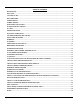
TABLE OF CONTENTS INTRODUCTION..........................................................................................................................................................................3 HEAT LOSS.................................................................................................................................................................................3 LOCATION OF UNIT .........................................................................................................
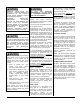
IMPROPER INSTALLATION MAY CREATE A CONDITION WHERE THE OPERATION OF THE PRODUCT COULD CAUSE PERSONAL INJURY OR PROPERTY DAMAGE. IMPROPER INSTALLATION, ADJUSTMENT, ALTERATION, SERVICE OR MAINTENANCE CAN CAUSE INJURY OR PROPERTY DAMAGE. REFER TO THIS MANUAL FOR ASSISTANCE OR ADDITIONAL INFORMATION, CONSULT A QUALIFIED INSTALLER, SERVICE AGENCY OR THE FUEL SUPPLIER.
HORIZONTAL INSTALLATION WML-C AND MPL-B furnaces models are assembled and shipped ready for installation in the down-flow position. The furnace may be installed in either of the horizontal positions; warm air discharging left or warm air-discharging right by following these steps: 1. Rotate the furnace 90° to the desired position. 2. Remove the three nut and washer sets fastening the oil burner assembly to the furnace. Rotate the oil burner assembly to be in the normal upright position. 3.
through a refrigeration unit unless the unit is specifically approved for such service. Generally, a six-inch clearance between the air conditioning evaporator coil and the heat exchanger will provide adequate airflow through the evaporator coil. The blower speed must be checked and adjusted to compensate for the pressure drop caused by the evaporator coil. Refer to Appendix B for recommended wiring and electrical connections of the air conditioning controls.
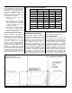
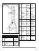
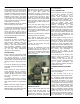
Fig. 2: Common Chimney Problems Can be found by light and mirror reflecting conditions in chimney. Use weight to break and dislodge. Joist protruding into chimney. Lowering a light on an extension cord. Must be handled by competent masonry contractor. F Break in chimney lining. Smoke test build smudge fire blocking off other opening, watching for smoke to escape. Must be handled by competent masonry contractor. G Collection of soot at narrow space in flue opening. Lower light on extension cord.
OPTIONAL SIDE WALL VENTING Certain WML-C AND MPL-B furnace models are manufactured to be installed as sidewall vented units. Please refer to Direct Venting Instructions, P/N 28888 included with the Vent Kit for details. Sidewall Venting (Direct Venting) requires the use of specific oil burners; the Beckett AFII, or the Riello 40BF. Please refer to Appendix A, Tables A2, and A4. Note: Sidewall venting requires special attention to combustion air supply.
main electrical panel; however, accessory equipment such as electronic air cleaners and humidifiers may be included on the furnace circuit. Although a suitably located circuit breaker can be used as a service switch, a separate service switch is advisable. The service switch is necessary if reaching the circuit breaker involves becoming close to the furnace, or if the furnace is located between the circuit breaker and the means of entry to the furnace room.
trunk ducts. These systems may require modification to provide some resistance to the airflow to prevent over-amping of the direct drive blower motor. Selecting a lower blower speed may correct this problem. Direct drive blower speeds are adjusted by changing the "hot" wires to the motor winding connections. Please refer to wiring diagram in Appendix B or the wiring diagram label affixed to the furnace. THE NEUTRAL WIRE (normally the white wire) IS NEVER MOVED TO ADJUST THE BLOWER SPEED.
BURNER ELECTRODES PROCEDURE: Correct positioning of the electrode tips with respect to each other, to the fuel oil nozzle, and to the rest of the burners is essential for smooth light ups and proper operation. The electrode tips should be adjusted to a gap of 5/32”, 1/16” ahead of the nozzle, 5/16” above the centerline of the nozzle. The “Z” dimension (front edge of the burner head to the front face of the nozzle is 1-1/8 inches. Start the burner and allow it to run at least ten minutes.
used in conjunction with multi-meters with temperature measurement capabilities. anywhere within the heating system which may cause some concern or annoyance to the home owner, etc. The return air should be measured at a point where the thermometer will be well within the air stream near the furnace return air inlet. Actual location is not particularly critical; however, avoid locations where the temperature readings could be affected by humidifier bypass ducts, the inside radius of elbows, etc.
should be checked to ensure that all fan speeds are operating properly. OPERATING INSTRUCTIONS Before Lighting Open all supply and return air registers and grilles. Open all valves in oil pipes. Turn on electric power supply To Light Unit Set the thermostat above room temperature to call for heat. The burner should start. NOTE: It may be necessary to press the RESET button on the primary combustion control relay. There will be a fan on time delay before the circulating fan is energized.
APPENDIX A- WML-C AND MPL-B BURNER SET UP WML-C AND MPL-B furnaces may be used with the following oil burners. Please note: The Beckett AF, and Riello 40F oil burners are for applications using indoor air for combustion only. For sidewall venting applications utilizing outdoor air for combustion, use the Beckett AFII or the Riello 40BF (Balanced Flue) oil burners only.
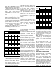
Table A-4 Riello Balanced Flue (BF) Burner Set-Up Riello Balanced Flue Series Oil Burners (For use with sidewall vented units using outdoor combustion air) Furnace Model Output BTU/Hr Burner Model Nozzle Pump Pressure Flow Rate Turbulator Setting WML-60CRB 59,500 40BF3 0.50 / 60°W 105 PSIG 0.51 USGPH 1.0 WML-80CRB 75,000 40BF3 0.60 / 60°W 115 PSIG 0.65 USGPH 1.5 WML-90CRB 85,600 40BF3 0.65 / 60°W 135 PSIG 0.
Table A-6 Direct Drive Blower Set-Up Blower Set-Up Cooling Capacity Furnace Model Blower WML-60C GT10 DD Low ½ HP Med-Low ½ HP 3 ½ HP 763 – 1505 WML-80C GT10 DD Med-Low ½ HP Med-High ½ HP 3 ½ HP 763 – 1505 WML-90C GT10 DD Med-High ½ HP High ½ HP 3 ½ HP 763 – 1505 MPL-90B GT12-10DD Low ¾ HP Med-High ¾ HP 3 ¾ HP 1185 – 1553 MPL-100B GT12-10DD Med-High ¾ HP High ¾ HP 3 ¾ HP 1185 – 1553 ¾ HP 1185 – 1553 ¾ HP 1185 – 1553 0.20 in. w.c. Speed 0.50 in. w.c.
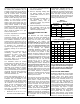
Table A-9 General Dimensions (Inches) Plenum Openings Cabinet Filter Width A Depth B Height C Supply DxE Side Bottom Flue Diameter H WML-C 22 22-1/8 55-1/4 19 x 19 18 x 18 18 x 18 5 Permanent 20 x 20 x 1 265 MPL-B 22-1/4 22-1/4 62 20-1/2 x 201/2 18 x 18 18 x 18 6 Permanent 20 x 20 x 1 292 Furnace Model WML-C & MPL-B Down flow Return Type Size Shipping Weight WML-C & MPL-B Horizontal 16 30318 R4 9/9/2005
APPENDIX B: WIRING DIAGRAMS Beckett AF Burner Wiring Diagram 17 30318 R4 9/9/2005
Beckett AFII Burner Wiring Diagram 18 30318 R4 9/9/2005
Riello 40F3 and F5 Burner Wiring Diagram 19 30318 R4 9/9/2005
Riello 40BF3 Burner Wiring Diagram 20 30318 R4 9/9/2005
OPERATION OF OIL BURNER Once the furnace flue pipe, electrical and oil line connections have been made, use the following instructions to set the burner: Shut off the electrical power to the furnace. Install an oil pressure gauge to the pressure port on the oil pump. (Refer to the oil pump specification sheet included with the burner instructions). Restore electrical power to the furnace. Start the furnace and bleed all air from the fuel oil lines. Close the purge valve and fire the unit.
APPENDIX C-R7184 TROUBLESHOOTING R7184 DETAILED SEQUENCE OF OPERATION (FIGURE 7) Power is applied to unit. The R7184 completes a self-diagnostic procedure. If no light or flame is present, and unit passes its self-diagnostic procedure, the control enters into the idle mode. Thermostat calls for heat: A) Safety check is made for flame (4 second delay). 1) If flame is not present, the R7184 will apply power to the burner motor and igniter. 2) If flame is present, the control remains in the idle state.
R7184 INTERRUPTED ELECTRONIC OIL PRIMARY CONTROL FIGURE 7 ELECTRONIC FAN TIMER BOARD ON CONTROL PANEL FIGURE 8 23 30318 R4 9/9/2005
IDLE STATE THERMOSTAT CALLS FOR HEAT SAFETY CHECK FOR FLAME (5 SEC.) R7184 SEQUENCE of OPERATION REMAINS IN IDLE STATE NO FLAME FLAME BURNER MOTOR & IGNITOR START 10 SEC. SAFETY CHECK FOR FLAME (5 SEC.
Table C-1: ELECTRONIC FAN TIMER BOARD (EFT) DETAILED SEQUENCE OF OPERATION Mode HEAT Action System Response Thermostat calls for heat. ("W" terminal is energized). a. EFT closes oil primary control T - T connections). b. Ignition system and R7184 oil primary control start the furnace. Oil flows as long as the oil primary control senses flame. c. Burner motor is energized and heat "fan on" delay timing begins. When timing is complete, the circulator fan is energized at heat speed.
R7184 LED DIAGNOSTIC LIGHT TROUBLESHOOTING The LED diagnostic light has several functions. It indicates the state or mode in which the oil burner is operating. It will also indicate fault conditions, and help determine cad cell resistance while the burner is operating. IMPORTANT: Due to the potential hazard of line voltage, only a trained, experienced service technician should perform the troubleshooting procedure. NORMAL CONDITIONS: Check the diagnostic light for indications of burner condition.
Table C-3: R7184 TROUBLESHOOTING Condition: Burner motor does not start when there is a call for heat. Procedure Status Corrective Action 1. Check that limit switches are closed and contacts are clean. N/A N/A 2. Check for line voltage power at the oil primary control. Voltage should be 120 Vac between the black and white lead wires on the oil primary control. N/A N/A 3. Check indicator light with burner off, no call for heat (no flame).
Condition: Burner starts then locks out on safety with indicator light flashing at 1/2 second on, 1/2 second off. (Cont.) Procedure 8. 9. Listen for spark after burner turns on (after 2 second delay). Check indicator light after flame is established, but before oil primary control locks out. 10. Check cad cell sighting for view of flame. a. Disconnect line voltage power and open line switch. b. Unplug cad cell and clean cad cell face with soft clothe. Check sighting for clear view of flame.
TABLE C4: SYSTEM AND GENERAL TROUBLESHOOTING Problem Possible Cause Remedy Thermostat not calling for heat. Check thermostat and adjust. Also, check thermostat for accuracy; if it is a mercury switch type, it might be off level. No power to furnace. Check furnace switch, main electrical panel furnace fuse or circuit breaker. Also look for any other hand operated switch, such as an old poorly located furnace switch, which was not removed during furnace replacement. Thermostat faulty.
TABLE C-4: SYSTEM AND GENERAL TROUBLESHOOTING continued Problem Oil burner nozzle Excessive consumption. sputtering fuel at Possible Cause Remedy Electrodes out of adjustment or defective. Check electrode settings. Check electrodes for dirt build-up or cracks in porcelain. Poor transformer high voltage connections or defective transformer. Check contacts between the igniter and electrodes. If OK, replace the igniter Fuel oil filter clogged.
TABLE C-4: SYSTEM AND GENERAL TROUBLESHOOTING continued Problem Supply air temperature too hot. Supply air temperature too cool. Supply air temperature too cool during first moments of furnace cycle. Possible Cause Remedy Airflow blocked or dirty air filter. Clean or replace air filter. Insufficient airflow. Check all dampers. Open closed dampers including registers in unused rooms. Check system temperature rise. If temperature rise is too high, speed up blower fan. Excess airflow.
PARTS LISTING: COUNTERFLOW HORIZONTAL MODEL: WML C Ref. No. 1 2 3 4 5 6 7 8 9 10 11 12 13 14 15 16 17 18 19 20 21 22 23 24 25 26 27 28 29 30 Description PART NO.
PARTS LISTING: COUNTERFLOW HORIZONTAL MODEL: WML C Ref. No. 31 32 33 34 35 36 37 Description PART NO. Auxiliary Limit 60T11BOF L140º F Transformer Control Panel Wire Harness, Junction Box to Control Wire Harness, Supply Limit Cover, Left Limit Cover, Right 29198 27738 30190 30264 29366 30240 30195 PARTS LISTING: COUNTERFLOW HORIZONTAL DIRECT VENT MODEL: WML CB2U Ref. No. Description PART NO. All parts are the same as listed on the previous pages for Model WML-C except where noted below.
30318 R4 9/9/2005
PARTS LISTING: COUNTERFLOW HORIZONTAL MODEL: MPL Ref. No.
PARTS LISTING: COUNTERFLOW HORIZONTAL MODEL: MPL Description Ref. No. 37 Beckett oil Burner AF76XN Burner Motor 1/7 HP 3450 RPM PSC Beckett Clean-cut Oil Pump A2EA6520 Solid State Ignitor FRANCE 10SAY-04 Primary Combustion Control R7184A Air Tube Combination AF76XN Flame Retention Head (MPL 80, to 120) Flame Retention Head (MPL 130) Nozzle 1.00 / 60º A (MPL 120) Nozzle 1.
30318 R4 9/9/2005
HOMEOWNER’S REFERENCE TABLE Model No. Serial No. Date Installed Contractor Contact Address Postal Code Telephone No. After Hours No. FUEL SUPPLIER Fuel Oil Supplier Contact Telephone No. After Hours No. IF DIFFERENT FROM INSTALLATION CONTRACTOR: Service Tech. Telephone No. After Hours No.
NOTES: 39 30318 R4 9/9/2005
6800 Base Line, Wallaceburg, Ontario, N8A 5E5, Can. Tel: (519) 627-0791 Fax: (519) 627-4719 2201 Dwyer Avenue, Utica, New York, 13504, USA. Tel: (315) 797-1310 Fax: (315) 724-9319 85 Middle Road, Dunkirk, New York, 14048, USA Tel: (716) 366-5500 Fax: (716) 366-1209 www.ecrinternational.