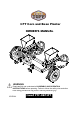
3 PT Corn and Bean Planter OWNER’S MANUAL WARNING: Read carefully and understand all ASSEMBLY AND OPERATION INSTRUCTIONS before operating. Failure to follow the safety rules and other basic safety precautions may result in serious personal injury.
Thank you very much for choosing this product! For future reference, please complete the owner’s record below: Model: ___ FTF-CBP3PT __ Purchase Date: _______________ Save the receipt, warranty and these instructions. It is important that you read the entire manual to become familiar with this product before you begin using it. This machine is designed for certain applications only. The manufacturer cannot be responsible for issues arising from modification.
WORK AREA •Keep work area clean, free of clutter and well lit. Cluttered and dark work areas can cause accidents. •Keep children and bystanders away while operating the planter. Distractions can cause you to lose control, so visitors should remain at a safe distance from the work area.
HOBBY SEED PLANTER (Patent) ASSEMBLY AND OPERATING MANUAL PRE-ASSEMBLY: Approximate assembly time of this product is 1 hour. Helpful Tip: Read all instructions before starting to assemble. WARNING: TG or Field Tuff will not be held liable for any damages, losses or injury, due to the misapplication or misuse of this product or for any other reason. Proper eye and hand protection must be worn at all times times.
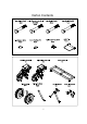
Carton Contents 5
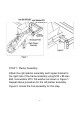
STEP 1: Planter Assembly Attach the right planter assembly and hopper bracket to the right g side of the frame assembly y using g M10 x 85 Hex Bolt, lock washer Ø10, flat washer as shown in Figure 1. Repeat above procedure for the left planter assembly. Figure 2. shows the final assembly for this step.
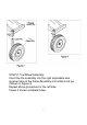
STEP 2: Tire/Wheel Assembly Insert the tire assembly into the right adjustable axle receiver tube of the frame Assembly and install Lock pin. (Shown in Figure 3) Repeat above procedure for the left side. Figure 4 shows completed step.
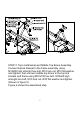
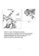
STEP 3: Top Link Bracket and Middle Top Brace Assembly. Connect top link bracket to the frame assembly using M10x85 high strenght hex bolt, M10 lock nut, Ø10 flat washer and tighten, then connect middle top brace to the t op link bracket and frame using M10x100 hex bolt, M10x85 high strength hex bolt, M10 lock nut, Ø10 flat washer and tighten. (Shown in figure 5) Figure 6 shows the assembled step.
STEP 4: Lower Link Brackets Assembly Install the Lower Link Bracket onto the frame assembly using M10x65 hex bolt, M10 nylon lock nut,Ø10 flat washer and tighten. (As shown in figure 7) Figure 8 shows the assembled step step.
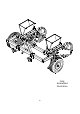
Fully Assembled Illustration 10
Figure 11 Adjusting j g Row Width 1.To adjust the row width loosen the 4 hex bolts item 15, that fasten the planter assembly to the rear frame assembly. Measuring from the middle of frame, move the planter in or out to half the row width. I.e.24” row width measures 12” from middle frame to the planter assembly. Repeat for opposite planter assembly. See figure 11.
Figure 12 Setting Planter Seed Depth 1. Attach planter to the tractor with 3pt. Lower Planter to ground and adjust top link so that planter is level. 2. Lower planter to ground so that coulters sit on flat level surface. See figure 13 of next page. 3. Raise wheel assembly and place 1-1/2’’spacer under wheel. Install lock pin into the closest holes in square tube. Repeat for opposite side side. The planter is now set to plant at the 1-1/2’’ 1 1/2 depth.
Coulter Adjustment 1.To move coulter assembly down raise planter off of flat surface, loosen the u-Bolts item 20 and lower coulter assembly down. Retighten U-bolts. See figure 13. Repeat steps 1 through 3 again, setting planter seed depth.
Adjustment for Seed Size The wheel handle item 29 on the side of planter assembly is used to adjust the size of the pocket that the seed will fall into and be metered out of the hopper assembly. Turning the wheel handle clockwise makes the pocket smaller and counter clockwise enlarges it. See figure 14. Note: Opening up the pocket so more than one seed will fit into pocket will give more population of plants.
Concept of operation of planter. As the planter is pulled forward the black steel wheel is ground driven. The black steel wheel drives the plastic seed hub inside the hopper. As the plastic hub turns the seed drops into the seed pockets pockets. The seed then travels out the hopper via the seed pocket and then is dropped into seed tube. The seed then is placed into the ground and then is covered up by the rear roller.
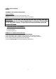
21 84 85 86 87 88 89 86 68 89 86 67 88 85 87 60 17 18 59 60 17 18 86 58 17 18 84 21 72 65 72 66 68 60 17 18 69 62 73 71 70 72 63 17 18
Part List Part No.
For replacement parts and technical questions, please call 1-218-943-6296 WARRANTY One-year limited parts warranty TG PO Box 203 Miltona MN 56354 Miltona, MADE IN CHINA 20