H-SERIES FUEL TRANSFER PUMPS FR1200, FR2400, FR4200, FR4400, FR600, SD1200, SD600 Installation and Operation Manual MADE IN USA
| INSTALLATION AND OPERATION MANUAL H-SERIES FUEL TRANSFER PUMPS Table of Contents Limited Warranty Policy........................................................................ 2 Thank You! About This Manual................................................................................ 2 Thank you for your loyalty to the Fill-Rite® brand of fuel transfer pumps. Your safety is important, so please read and thoroughly understand the procedures set forth in this manual.
| INSTALLATION AND OPERATION MANUAL H-SERIES FUEL TRANSFER PUMPS H-Series Fuel Transfer Pumps Have the Following Features • Adjustable Electrical Junction Box Rotates 180 degrees to provide ease of electrical wiring installation in tight quarters no matter the inlet bung location • Reliable, Heavy-Duty Power Switch Lever Features a cast metal stop that withstands heavy use in the most rugged environments • Locking Bar Defense Elongated bar simplifies the pad locking process to prevent theft • Focused Com
| H-SERIES FUEL TRANSFER PUMPS INSTALLATION AND OPERATION MANUAL Safety Information To ensure a safe installation and proper equipment operation, please read, understand, and adhere to all DANGER/WARNING/CAUTION and other NOTICES. Never smoke around or near a fuel tank or transfer pump. Open flames or a spark when pumping a flammable liquid will result in a fire. Improper electrical wiring or installation will result in serious injury or death.
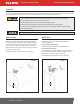
| INSTALLATION AND OPERATION MANUAL H-SERIES FUEL TRANSFER PUMPS Installation Your Fill-Rite pump is designed to be mounted on a fuel tank via a threaded inlet flange supplied with the pump. Typical installations are shown in Diagram 1 and 2. Your pump features an integral bypass valve to recirculate the fluid when the pump is operating with the nozzle closed. Do not use additional check valves or foot valves unless they have a proper pressure relief valve built into them.
| INSTALLATION AND OPERATION MANUAL H-SERIES FUEL TRANSFER PUMPS Installation Procedure Step 1: (Optional) Inlet Flange Removal Loosen (4) 1/4" bolts using 7/16" wrench or socket. Detach inlet bung from pump, retain bolts, screen, and gasket. Step 2 Step 3 Step 2: Using either included suction pipe or custom pipe, thread pipe into inlet bung 1.5 to 2.5 turns past hand tight with pipe wrench. Use appropriate sealant for fuel transfer. Step 3: Thread inlet bung with attached suction pipe onto tank 1.
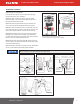
| INSTALLATION AND OPERATION MANUAL H-SERIES FUEL TRANSFER PUMPS 12V DC and 24V DC Wiring Instructions FR1200 / FR2400 / FR4200 / FR4400 / SD1200 Series DC Transfer Pump Electrical wiring should be performed ONLY by a licensed electrician in compliance with local, state, and national electrical codes (NEC/ANSI/NFPA 30, NFPA 30A, and NFPA 70) as appropriate to the intended use of the pump. Threaded rigid conduit, sealed fittings, and conductor seal should be used where applicable.
| INSTALLATION AND OPERATION MANUAL H-SERIES FUEL TRANSFER PUMPS Instructions Before Proceeding with DC Wiring The pump needs to be electrically bonded to a vehicle frame for mobile tanks or a ground rod for stationary tanks. To electrically bond pump for mobile application, remove the external factory installed green bonding screw located on the junction box cover (Diagram 3). Insert this screw through eyelet of furnished green bonding wire assembly and refasten it securely to the junction box.
| INSTALLATION AND OPERATION MANUAL H-SERIES FUEL TRANSFER PUMPS Mobile Tank Wiring to a Non-Vehicle System While rare, there are instances where a 12V or 24V DC Fill-Rite fuel pump does not operate from a vehicle’s electrical system. In these cases, we recommend calling Tuthill Technical Service at 1-800-634-2695 (M-F, 8am-6pm EST/EDT) to discuss your specific situation. Most of these applications will require equipment not supplied by Tuthill.
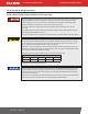
| INSTALLATION AND OPERATION MANUAL H-SERIES FUEL TRANSFER PUMPS 115V AC Wiring Instructions for FR600 / SD600 AC Fuel Transfer Pumps • All pumps will operate at the rated nameplate voltage. • AC power should be supplied to the pump from a dedicated circuit with a 15 amp circuit protection. No other equipment should be powered by this circuit. • Wiring must be of sufficient size to carry the correct current for the pump.
| INSTALLATION AND OPERATION MANUAL H-SERIES FUEL TRANSFER PUMPS 115V AC Wiring Procedure 1. Remove the junction box cover and straighten the wires to make sure the stripped wire ends are accessible outside the junction box. 2. Install rigid conduit and appropriate wiring from power source to the junction box to maintain the explosion-proof integrity. 3. Connect the pump wires to the power supply lines according to the wiring diagram.
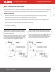
| H-SERIES FUEL TRANSFER PUMPS INSTALLATION AND OPERATION MANUAL Operation Instructions Always keep the nozzle in contact with the container being filled during the filling process to minimize the possibility of static electricity build up. A spark around flammable vapors will cause an explosion resulting in death or serious injury. 1. If equipped, reset meter to “0” (do not reset while in use as this will cause damage to the meter). Diagram 7 2. Remove dispensing nozzle from nozzle boot. 3.
| Troubleshooting Symptom Pump won’t prime Low capacity Pump runs slowly Motor stalls, fuse blows, thermal protector trips repeatedly Motor overheats Motor inoperable Fluid leakage Pump hums but will not operate H-SERIES FUEL TRANSFER PUMPS INSTALLATION AND OPERATION MANUAL (continued) Cause Cure Suction line problem Check for leaks or restrictions in suction line Bypass valve open Remove and inspect valve; must move freely and be free of debris Vanes sticking Check vanes and rotor slots
| INSTALLATION AND OPERATION MANUAL H-SERIES FUEL TRANSFER PUMPS Specifications and Models A series of fuel transfer pumps with UL/cUL certifications that are compatible with gasoline, diesel fuel, blended fuels such as biodiesel up to 20%, gasoline with up to 15% ethanol, mineral spirits, and kerosene.
| H-SERIES FUEL TRANSFER PUMPS FR1200, FR2400, FR4400, FR600, SD1200, and SD600 INSTALLATION AND OPERATION MANUAL (Dimensions displayed in inches) 13.0 8.4 2.5 3.4 4.3 11.1 FR4200 (Dimensions displayed in inches) 13.7 8.4 2.5 4.2 4.3 11.8 fillrite.com | tuthill.
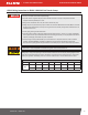
| INSTALLATION AND OPERATION MANUAL H-SERIES FUEL TRANSFER PUMPS H-Series Model Information: FR1200, FR2400, FR4200, FR4400, FR600, SD1200, SD600 Model Number Nozzle Hose FR1204H Meter Manual 12' FR1210HA Auto Gasoline 12' FR1210HA1 Auto Diesel 12' FR1210HARC Auto Arctic 15' FR1211H Manual 12' 807C FR1211HL Manual 12' 807CL FR1211HLN 807CL FR1211HN 807C Manual 12' FR2404H 12' FR2411H Manual 12' 807C FR2411HL Manual 12' 807CL FR4204H 12' Auto Arctic 20' FR4210HB U
| H-SERIES FUEL TRANSFER PUMPS INSTALLATION AND OPERATION MANUAL 1200 Series Performance Curve 2400 Series Performance Curve fillrite.com | tuthill.
| H-SERIES FUEL TRANSFER PUMPS INSTALLATION AND OPERATION MANUAL 4200 Series Performance Curve 4400 Series Performance Curve fillrite.com | tuthill.
| INSTALLATION AND OPERATION MANUAL H-SERIES FUEL TRANSFER PUMPS 600 Series Performance Curve Accessories METER STRAIGHT PIPE FILTER HEAD STREET ELBOW STRAIGHT PIPE SWIVEL NOZZLE FILTER HOSE Proper Accessory Configuration fillrite.com | tuthill.
| Accessories (continued) Accessory Outlet Size Series Manual Hi-Flow Nozzle INSTALLATION AND OPERATION MANUAL H-SERIES FUEL TRANSFER PUMPS Arctic Automatic 1" FRHMAN075S FRHMN1005 Gasoline/Diesel N075UAU10 N100DAU12 Red Boot N075DAU10 N100DAU12G Green Boot FRNA075DAU10 FRNA100DAU00 Cold Weather (-40˚F/˚C) N100DAU13 Red Boot N100DAU13G Green Boot N100DAU13Y Yellow Boot Ultra Hi-Flow 12', UL Rated 700F3135 300F7773 12' FRH07512 FRH10012 14' FRH07514 FRH10014 20' FRH07
| H-SERIES FUEL TRANSFER PUMPS INSTALLATION AND OPERATION MANUAL Pump Service Kits # Kit Description Parts 1 KIT120BD* BioDiesel Kit O-ring, inlet and bypass cap seals, bypass valve poppet 2 KIT120RGG Rotor and Vane Kit Rotor cover, rotor, vanes, rotor key, O-ring seal, attaching hardware 3 KIT120JCH Junction Cover Kit Junction cover, seal, fasteners 4 KIT120SL Seal Kit O-ring, shaft seals, retainer clip 5 KIT120BV Bypass Service Kit Bypass valve, valve spring, bypass cap, O-ring
Safety Testing Approvals Motor Tag Information The Fill-Rite line of pumps have been safety tested for regulatory compliance. This product family is approved by Underwriters Laboratories (UL). The motor tag on your Fill-Rite pump contains important technical and performance information. Be certain this label remains affixed to the pump at all times. Tuthill Corporation 8825 Aviation Drive Fort Wayne, Indiana 46809 USA P (800) 634-2695 (+01) 260-747-7524 F (800) 866-4681 tuthill.com | fillrite.