
Full Product Manual


fillrite.com | tuthill.com
8
| H-SERIES FUEL TRANSFER PUMPS
INSTALLATION AND OPERATION MANUAL
Instructions Before Proceeding with DC Wiring
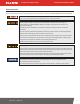
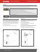
The pump needs to be electrically bonded to a vehicle frame for mobile tanks or a ground rod for stationary tanks. To electrically bond pump for mobile
application, remove the external factory installed green bonding screw located on the junction box cover (Diagram 3). Insert this screw through eyelet of
furnished green bonding wire assembly and refasten it securely to the junction box. The other end of the wire is to be stripped of insulation and the bare wire
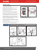
securely bonded to the vehicle or on/off road trailer frame for mobile tanks (Diagram 4). For bonding with stationary tanks, attach a ground wire to a ground
rod and the tank itself (Diagram 5). The distance may be greater than the supplied grounding wire.
DC Wiring Instructions
Diagram 5
ATTACH GROUND WIRE
TO GROUND ROD
1. Remove pump’s electrical junction box cover and straighten the red and black wire.
2. Screw the furnished cable connector into 1/2" NPT conduit opening on the junction box.
3. Strip 3" of the outer covering from one end of the furnished electrical supply cable.* Be careful not to damage the black and red wire insulation.
4. Loosen cable connector nut and pass the stripped end of the furnished cable through the cable connector. Tighten the cable connector nut.
5. Strip 1/2" of the insulation from the ends of the red and black cable wires. Using the furnished wire nuts, connect the cable wires to the pump wires
matching the colors.
IMPORTANT: be sure no bare wire is exposed.
6. Fold wires into junction box and replace, making sure the cover gasket is in place. Make sure all screws are seated so there is no space between the
frame and the junction box (see Step 6 diagram on Page 6).
*12 AWG cable not supplied with pump only models
ATTACH GROUND WIRE TO VEHICLE BODY
½" NPT
CONDUIT HOLE,
THREADED
(2) T-25
TORX SCREWS
EXTERNAL GREEN
GROUND SCREW
JUNCTION
BOX GASKET
JUNCTION BOX CAP
(CAN BE ROTATED 180°)
EARTH GROUND
SYMBOL
Diagram 3 Diagram 4
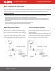
Mobile Tank Wiring to a Vehicle Electrical System
1. Before electrical installation, place the switch lever into the OFF position to prevent accidental spillage once power is engaged to the motor.
2. Pass the electrical wires to the source of the vehicle power system, supporting as necessary and protecting them from sharp edges, heat, or anything
that could cause damage.
3. To determine if the vehicle electrical system is negative (-) or positive (+) ground, check the battery marking of the terminal that is wired to the vehicle
frame or motor block. The red wire from the pump will connect to positive battery post and the black wire from the pump will connect to negative battery
post. These instructions focus on COMMON negative ground systems. UNCOMMON positive systems are a rare occurrence. Reference the drawing on
Page 9 for information on positive ground systems.
4. Tuthill requires installing a fuse holder and fuse (not provided) for protection of the purchased pump. Attach one end of the fuse holder to the end of
the ungrounded wire, making a solid connection. The other end of the fuse holder is then attached to the ungrounded side of the battery, as close to
the battery as possible. Make a solid electrical connection to the grounded side of the battery with the remaining wire. Utilizing a battery terminal
connection (not provided by Tuthill) is required for completion of the electrical circuit.
5. Check all connections to make sure they are connected per instructions and all electrical codes. Install fuse (30 amp fuse for 12V DC; 20 amp fuse for
24V DC) into the fuse holder. Installation is now complete.