TS Series S & E●● assy. 316 Stainless Steel, Electronic Output Manual FPPMS12, Rev. 2008-03 Installation, Operation & Parts Manual Flow meter P/No.: __________________ Flow meter S/No.: __________________ MODEL Register TS10C none TS15C set up for: Accessories none Strainer, standard TS20C ELNC Air Eliminator TS30C EMR³ 1-stage Solenoid Valve EPSON Printer 2-stage Solenoid Valve other: Register components are supported with separate manuals, also supplied with the flow meter.
INDEX Section . Page FPP Meters and Principle of Operation . . . . . . . . . . . . . . . . . . . . . . . . . . . . . . . . 1 . 3 Safety Instructions . . . . . . . . . . . . . . . . . . . . . . . . . . . . . . . . . . . . . . . . . . . . . . . . . 1 . 4-5 Installation & Operation Procedures . . . . . . . . . . . . . . . . . . . . . . . . . . . . . . . . . . 1 . 5 Start-Up & Operation . . . . . . . . . . . . . . . . . . . . . . . . . . . . . . . . . . . . . . . . . . . . . . . 1 .
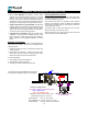
TS Series, Principle of Operation Only 2 moving parts. Patented ‘Waveform’ oval gears = sustained accuracy with a minimum of maintenance. No metal-to-metal contact in measuring chamber or in bearings. The lowest differential pressure values amongst rotary PD meters. => Lower Cost of Ownership! About FPP Meters We thank you for purchasing an FPP Meter for liquid measurement service. FPP Meters, formerly Fluid Power Products, is now a trade name of Tuthill Transfer Systems.
Installation, Start-Up & Operation SAFETY INSTRUCTIONS OPERATING TEMPERATURE TS Series assemblies are rated for: F●● assy See register temperature rating W●● assy -40°F/+225°F (-40°C/+107°C). Make sure that all necessary safety precautions have been taken, including proper clothing, personal safety equipment and fire safety equipment if required. However: Before Start-Up of the Flow Meter, make certain that: 1. The meter is properly mounted, secured and piped. 2. All connections are tight. 3.
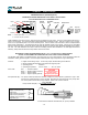
Installation, Start-Up/Operation & Direction of Flow When an Air Eliminator is included in the flow meter assembly, the strainer/air eliminator must be in horizontal position, since the air eliminator operates on a gravity principle. A few drops of liquid may be expelled when the air eliminator vents, so vent ports should be piped back to storage or to a collection tank (sloping towards the tank).
TS Series - Pulse Pick-Ups Hall Effect Sensor (standard pulser) FLAME PROOF RATED SENSORS EEx d FOR ZONE 1 APPLICATIONS.
TS Series - Pulse Pick-Ups, continued Hall Effect Sensor (standard pulser) TESTING FOR HALL EFFECT PULSER OPERATION There are three system components, which must be examined, to determine whether lack of pulse signal is caused by: The flow meter. The pulser. The electronic register. 1. Verify that there is power to the electronic register. 2. Confirm that the system is filled with liquid, and that liquid is flowing. 3.
Flow Meter Calibration TS Series meters in E●● & S●● assembly have an internal pulser. The pulse signal generated by the flow meter, can be fed directly to most electronic registers. In such assemblies, flow meter calibration (or re-calibration) is through correction of the K Factor (number of pulses/unit volume) in the electronic register.
Flow Meter Specifications Liquid Viscosity³: With standard LV rotors, meters may be used to full nominal capacity up to 300 cPs (1500 SSU). When viscosity can exceed 300 cPs (1500 SSU), high viscosity (HV) rotors, code I (or J) are strongly recommended.
Trouble Shooting the Flow Meter Installation, Maintenance & Service must be performed by personnel: A. Qualified to work on this type of equipment. B. Familiar with all applicable local codes and ordinances covering the type of service, where the flow meter is used (gasoline, LPG, etc.). Reduced Flow Rate Strainer basket partially blocked. Clean the basket. Pump not functioning correctly. Repair pump. Valve stuck in partially closed position. Check valves and repair.
Flow Meter - Disassembly and Repair Installation, Maintenance & Service must be performed by personnel: A. Qualified to work on this type of equipment. B. Familiar with all applicable local codes and ordinances covering the type of service, where the flow meter is used (gasoline, LPG, etc.). Avoid pipe strain and stress when making flow meter repairs. The weight of the pipe and the flow meter must be supported independently.
Flow Meter - Disassembly and Repair A. Pulser O-ring (15), or Pulser (16) First relieve system pressure and drain the flow meter. 1. If included, remove 4 screws (23 & 24) from the dust cover (22), and detach the dust cover. 2. Remove 3 retainer screws (18), and detach the retainer (17). The pulser (16) can now be removed, so the O-ring (15) can be replaced. The pulser can be placed at this time if necessary. Reassemble in reverse order, checking all O-ring seals for damage.
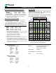
TS Series - Exploded View, Electronic Torque & Tool Chart IT E M 23 24 18 14 7 26 25 30 TS10C D E S C R IP T IO N Dust cover screw Tool Retainer plate screw Tool Torque specification Cover screw Tool Torque specification Post/Bearing plate screw Tool Torque specification Pedestal screw Tool Torque specification Cover drain plug Tool Companion flange screw Tool Torque specification TS15C 1/4" nut driver Hand tight Impact Battery Tool 8/32 19.8in-lbs 1/4" Allen 5/16-18 132in-lbs 5/32" Allen 10/32 31.
Parts Lists – TS10C, TS15C, TS20C & TS30C Parts Lists TS10C Meter case depth: Single piece rear cover & body Capacity 40 GPM 150 lpm It e m 1 D E S C R IP T IO N qty P a rt N o . TS15C TS20C TS20C TS30C 2.95" 75 mm 3.19" 81 mm 3.46" 88 mm 4.96" 126 mm 60 GPM 100 GPM 150 GPM 200-250 GPM 230 lpm qty P a rt N o . 380 lpm P art N o . qty 570 lpm qty P a rt N o . 760-1000 lpm P a rt N o . qty 1 MB9320 M e t e r B o dy & P o s t as s y.
Warranty Tuthill Transfer Systems (“Manufacturer”) warrants to each buyer of its FPP Meters products (the “Buyer”) for a period of 12 months from date of invoice or sales receipt, but in no event more than 18 months from date of manufacture, that goods of its manufacture (“Goods”) will be free from defects of material and workmanship.