
Owner's manual


Reduced Flow Rate
Strainer basket partially blocked. Clean the basket.
Pump not functioning correctly. Repair pump.
Valve stuck in partially closed position. Check valves and
repair.
Meter rotors (oval gears) partially ‘salted’ with chemical
deposits, slowing the movement. Clean the meter (see
page).
Product Flows, but the register does not record
Check power supply to the register.
Check the connections between the pulser and the elec-
tronic register.
Check pulser output. Replace pulser (or SCL) if needed.
If product is flowing, and the flow meter is generating a
pulse signal, the problem is in the electronic register.
Please refer to the manual for the electronic register.
Product Flows, register does not record correctly
If the error factor is constant, the flow meter is fine. The
likely cause is either:
Incorrect K Factor in the electronic register. Re-calibrate
the meter and correct the K Factor.
A constant problem with air getting into the system. Re-
view system design and control valves.
If the error is random, the likely cause is either:
Poor cable connections (insulation not trimmed, or stray
strands getting close to incorrect contacts). Inspect and
correct connections as necessary.
Valve leaking, allowing a portion of the system to drain.
Check & repair valves.
An intermittent problem with air in the system, combined
with inadequate air elimination. Review system design
and control valves.
Interference from other electrical equipment nearby, pos-
sibly combined with sub-standard cables.
Breaking Teeth on Rotors (Oval Gears)
This is a sign of hydraulic shock conditions in the system.
Common sources:
Starting or stopping flow too rapidly. Replace damaged
components and correct operational practices.
Pump by-pass not adjusted properly. Re-adjust as nec-
essary.
Leakage from End Covers
The seals (and possibly end covers) have been damaged
due to excessive pressure. There are two possible sources:
Starting or stopping flow too rapidly. Replace damaged
components and correct operational practices.
The flow meter is in a system, where it can be isolated
between two valves. Add a Thermal Relief Valve to bleed
off excess pressure when the temperature rises.
1 . 10
Trouble Shooting the Flow Meter
Installation, Maintenance & Service must be performed
by personnel:
A. Qualified to work on this type of equipment.
B. Familiar with all applicable local codes and ordi-
nances covering the type of service, where the flow
meter is used (gasoline, LPG, etc.).
Purpose
This high accuracy electronic positive displacement flow
meter is designed to provide reliable liquid measurement
with a minimum of service requirements.
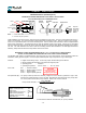
Functionality
The liquid moves the rotors, which in turn drive a multi-pole
disc magnet. Each 360º turn of the magnet generates 4, 6
or 12 pulses depending upon flow meter model, Quadrature
or single channel.
Assembly
The flow meter can be assembled for Left-to-Right, Bottom-
to-Top or Right-to-Left flow. The flow meter performs equal-
ly well in all directions. When Quadrature pulse signal is
used, it might be necessary to reverse leads if used for a
different flow direction from that originally intended.
Installation: See page 1.4
Maintenance
Electronic TS Series flow meters have no parts, which re-
quire replacement in the short term. The flow meter should
be re-calibrated periodically, and when meter wear factor
increases beyond the norm, the rotors should be replaced.
During service, also inspect the transfer gear/disc magnet
for wear. If worn, replace as a set.
Trouble Shooting & Service
Prior to opening or disassembly of any flow meter, all
internal pressure must be relieved and all liquid must be
drained. This must be done in accordance with applica-
ble company and local codes & ordinances.
Make sure that all necessary safety precautions have
been taken, including proper clothing, personal safety
equipment and fire safety equipment if required.
No Flow
Blocked strainer basket. Clean the basket.
Faulty or non-functioning pump. Repair pump.
Valve stuck in closed position. Check and repair valves.
Flow meter ‘frozen’ due to build-up of chemical salts (or
frozen water) inside the measuring chamber. Clean the
flow meter (see page ), and inspect for damage.
Meter jammed on a particle that has passed through a
damaged strainer basket. Remove particle and replace
rotors if necessary, replace strainer basket.