
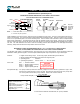
Owner's manual


both gears with a soft pencil for easy alignment when re-
installing the gears.
6. When re-installing the oval gears (2), place the upper
gear so that the slot for the coupling is horizontal.
7. Align the coupling in the bearing/gear plate (4), so that
the coupling is horizontal. Replace bearing/gear plate
assembly on dowel pins (6); reattach with 4 screws (7).
8. Replace cover O-ring (12), and reattach front cover (13),
pulser (16) and drain plug (25).
9. If included, re-attach RAD adaptor (19) with register, re-
place the dust cover (22) and re-seal the flow meter as-
sembly..
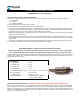
D. Post Plate assembly (3)
First relieve system pressure and drain the flow meter.
1. Remove cover screws (14) from flow meter rear cover
(29), and take the rear cover off. Discard the old cover O-
ring (12).
2. Remove 4 screws (7) from the post plate assembly (3),
and pull the post plate assembly straight back. If the post
plate assembly is stuck to meter body, gently tap with a
rubber mallet, or use a 5/16-8 x 1” jack bolt to push it free.
Do not use a hammer on the posts!
3. Inspect the inside of the post plate assembly (3) for scor-
ing (minor markings are acceptable). If the post plate
assembly is scored, or posts are worn, it must be re-
placed as a complete assembly.
4. Re-assemble in reverse order. Attach the post plate as-
sembly (3) to meter housing (1); it must attach to the side
marked with a dimple on the flat side. Align on dowel
pins (6) and fasten with 4 screws (7)..
5. Next replace rear cover O-ring (12), and re-install the rear
cover (29). Make sure that the drain plug (25) is located
at the bottom of the flow meter and that it is securely fas-
tened.
1 . 12
Flow Meter - Disassembly and Repair
A. Pulser O-ring (15), or Pulser (16)
First relieve system pressure and drain the flow meter.
1. If included, remove 4 screws (23 & 24) from the dust cov-
er (22), and detach the dust cover.
2. Remove 3 retainer screws (18), and detach the retainer
(17). The pulser (16) can now be removed, so the O-ring
(15) can be replaced. The pulser can be placed at this
time if necessary.
Reassemble in reverse order, checking all O-ring seals
for damage. Make sure that the pulser is installed with
mark in 12 o’clock position and that seal plug (25) is re-
placed and securely tightened.
B. Transfer Gear/Disc Magnet (10 & 11, repl as set)
C. Oval Gears (2)
E. Bearing/Gear Plate assembly (4)
First relieve system pressure and drain the flow meter.
1. If included, remove 4 screws (23 & 24) from the dust cov-
er (22), and detach the dust cover. Next remove the puls-
er as above; finally remove 4 screws (20) while support-
ing the register, and detach the RAD adaptor/register as a
complete assembly.
2. Remove front cover screws (14), and take the front cover
off. Discard the old cover O-ring (12). You now have
access to the bearing/gear plate assembly (4).
3. All the parts required to replace the transfer gear (10) &
the disc magnet (11) are supplied in a replacement kit
(see parts list). If the bearing is worn, replace the bear-
ing/gear plate assembly (4) also.
4. Remove 4 screws (7) from the bearing/gear plate assem-
bly (4). If it does not slip free, gently tap with a rubber
mallet, or use a 5/16-8 x 1” jack blot to push it free.
5. Once the bearing/gear plate assembly (4) is removed,
you can inspect, remove and/or replace the oval gears
(2). Before removing the oval gears, make a mark across