
Owner's manual


Reversing Direction of Flow
When a flow meter has been ordered for Left-to-Right flow,
but Right-to-Left is found to be more practical, the flow meter
can be re-assembled in the field.
The electronic flow meter can operate in either direction.
However, if the electronic register is utilizing the quadrature
pulse signal, the leads must be reconnected to reflect the
change in direction of flow.
The strainer (with or without air eliminator) can be trans-
ferred to the other side of the flow meter.
Solenoid valves can be moved to the other side of the flow
meter without any further modifications.
1 . 5
Installation, Start-Up/Operation & Direction of Flow
When an Air Eliminator is included in the flow meter
assembly, the strainer/air eliminator must be in horizontal
position, since the air eliminator operates on a gravity
principle. A few drops of liquid may be expelled when the
air eliminator vents, so vent ports should be piped back to
storage or to a collection tank (sloping towards the tank).
Thermal relief valves are recommended, and should be
installed whenever it is possible to block (isolate) the flow
meter between two valves. The pressure rise in a closed
system, from just a few degrees increase in temperature,
can be many times normal working pressure.
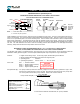
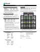
Connections for calibration should be provided during
installation. An easy means for diverting flow into a cali-
bration vessel (or master meter) should be considered.
Refer a diagram for the suggested installation is shown
below.
Start-Up & Operation
Very slowly fill the system with liquid, to avoid operating the
flow meter on air or vapor. This can be accomplished in the
following manner:
1. Throttle the meter inlet valve, and allow the system to fill
slowly by gravity.
2. Crack open the outlet valve. Start the pump, and then
slowly crack open the inlet valve, filling the meter slowly
before fully opening the inlet and outlet valves.
In normal operations:
Avoid sudden changes in temperature.
Avoid sudden changes in flow rate.
Gradually increase or decrease the flow rate.
TRV protects portion of system, which can be
isolated between valves IV1, CV1 & IV2.
Calibration Connection valves
Therm al Relief valve
IV1 & IV2:
C
V1 & CV2:
BPV :
TRV:
BY-PASS LINE
IV1 IV2
: IV2 & BPV closed, other valves open
TRV
: IV1 & IV2 closed (by-pass open)
During Calibration
: BPV, CV1 & CV2 closed
TEMPORARY MASTER METER
CV2
OPERATING FLOW M ETE
R
Normal Operation
BPV
Service/Maintenanc
e
CV1
Isolation Valves
By-Pass valve
(or Prover Tank)
OPTIONAL
The optimum flow meter installation should include
the components & features shown in this diagram.