
Owner's manual


TS Series - Pulse Pick-Ups, continued
1 . 7
Hall Effect Sensor (standard pulser)
TESTING FOR HALL EFFECT PULSER OPERATION
There are three system components, which must be examined, to determine whether lack of pulse signal is caused by:
The flow meter.
The pulser.
The electronic register.
1. Verify that there is power to the electronic register.
2. Confirm that the system is filled with liquid, and that liquid is flowing.
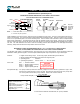
3. The functionality of the Hall Effect pulser can be confirmed with a volt meter and a permanent magnet. Remove the sen-
sor from the flow meter (refer to Flow Meter - Disassembly & Repair, part A). Expose the black and white (green) wires
in the sensor cable. Do this at a clean and dry location (table or service counter).
Measure the voltage between the white (green) wire, and the black wire; it should be nearly equal to the power supply
voltage provided on the red wire.
Pass the magnet across the tip of the sensor. The voltage must switch to nearly zero (less than 0.2 volts). If the magnet
will not actuate the sensor, then the sensor has failed. For two channel sensors, repeat the test with the green wire and
the black wire.
4. If the pulser works, then the failure is in the transfer gear (10)/disc magnet (11) on the bearing/gear plate (4). This can be
due to wear, or possibly due to excessive hydraulic shock conditions in the system.
Reed Switch Sensor, available with Intrinsically Safe certification
Optional pulser strictly for use with battery powered stand-alone registers. In ‘pulse meter’ service, either Hall Ef-
fect or Quadrature Hall Effect pulser must be used (depending upon requirements of the receiving instrument).
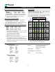
The Reed Switch pulser consists of a set of contacts hermetically sealed in a glass tube, protecting the contacts from dirt and
corrosion of the outside world. Contacts are actuated by an external magnetic field, provided by permanent magnets in an
internal multi-pole disc magnet.
Contact Rating:
Volts DC max. . . . . . . . . . . . : 30 VDC
Amps DC max. . . . . . . . . . . . : 0.01 A
Watts DC max. . . . . . . . . . . : 0.25 W
Initial Resistance . . . . . . . . . : 1.0 Ω
Operating Temperature range: -40°F to +300°F = -40°C to +150°C
D-Must Operate . . . . . . . . . . : 0.125” (3.2 mm)
D-Must Release . . . . . . . . . . : 0.400” (10.2 mm)
Cable specifications . . . . . . . : 24 AWG, 18” (45 cm) leads std.,
2 conductor (Red & Black)
TESTING FOR PULSER OPERATION - WARNING: Do Not use an Ohm-Meter to test the Reed Switch Sensor
Remove the sensor from the flow meter (refer to Flow Meter - Disassembly & Repair, part A). Expose the red and black
wires. Do this at a clean and dry location (table or service counter), or at the electronic register. Measure the voltage be-
tween the red and black wires. It should be equal to the voltage provided by the register. Pass a magnet across the tip of
the sensor, and observe that the voltage switches to zero (less than 0.2 volts). If the magnet cannot activate the switching of
the sensor, then the sensor has failed.