
Data Sheet


E
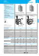
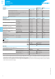
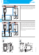
Functions for 72.42
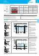
A1-A2 = Supply voltage
S1 (B1-B2) = Control signal 1
S2 (B3-B2) = Control signal 2
= Contact 1 (11-14) and
Contact 2 (21-24)
LED 1 = Output 1
LED 2 = Output 2
LED
Device in stand-by, output not activated
Output not activated, timing in progress
Output not activated (only functions M1/M2)
Output activated
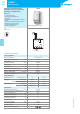
Wiring diagram
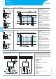
(MI) Outputs alternate on successive applications of
supply voltage
• Application of the supply voltage to A1-A2 forces
just one output contact to close, but the contact that
closes will alternate between 11-14 and 21-24 on each
successive application of the supply – ensuring even
wear across both motors.
• The other output contact can be forced closed by the
closure of either S1 or S2 - but to limit high current
surges the other motor cannot start within T seconds
of the first motor.
(ME) Outputs alternate according to control signal
• The supply voltage is permanently applied to A1-A2.
When closed, S1 forces just one output contact to
close. The contact that closes will alternate between
11-14 and 21-24 on each successive S1 closure -
ensuring even wear across both motors.
• If closed, S2 forces both output contacts to close
(irrespective of S1). However, to limit high current
surges, both motors cannot start within T seconds of
each other.
(M2) Output 2 (21-24) only
• Supply permanently applied to A1-A2.
• Closure of either S1 or S2 will close output contact
2(21-24). Use when load 1 (11-14) is out of service.
(M1) Output 1 (11-14) only
• Supply permanently applied to A1-A2.
• Closure of either S1 or S2 will close output contact
1(11-14). Use when load 2 (21-24) is out of service.
9
IV-2018,www.findernet.com
72
SERIES
72 SERIES
Monitoring relays