
Datasheet


X-2013, www.findernet.com
10
G
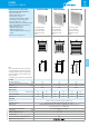
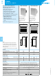
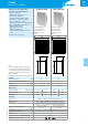
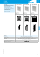
7F SERIES
Filter Fan (24…630)m
3
/h
7F
SERIES
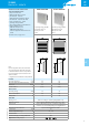
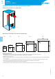
Mounting instructions for Filter Fans and Exhaust Filters
Mounting arrangement of Filter Fans and Exhaust Filters
Filter
Fan
Drilling template and mounting cut-outs for Filter Fans and Exhaust Filter
Size 1 Size 2 Size 3
Size 5
Size 4
Mounting and maintenance
1. Make the panel cut-out according to the size of the Filter Fan or Exhaust Filter in the sidewall of the cabinet as appropriate.
A template of the panel cut-out is included in the packaging of the Filter Fan or Exhaust Filter.
2. Make the electrical connection.
3. Mount by simply snapping the side-located lugs on the Filter Fan or Exhaust Filter into the panel cut-out (without using screws for sidewall thickness
of 1.2…2.4mm).
At other thickness it is recommended to mount the Filter Fan by the screws supplied (for size 1, the template shows the mounting cut-out only).
4. When screws are needed for the mounting, remove the plastic cover and fix the Filter Fan with the 4 screws supplied.
Then insert the filter mat and snap the plastic cover to the mounting frame.
5. During maintenance or when replacing the filter mat remove the plastic cover, replace the filter mat and snap on the plastic cover.