
Datasheet


II-2015, www.findernet.com
5
E
7P
SERIES
7P SERIES
Surge Protection Device (SPD)
SPD Type 2 Surge arrester range for single/
three phase AC systems and for DC systems
• Surge arrester suitable for AC and DC systems
to protect equipment against induced
overvoltage or switching transients
• To be installed at the boundary of LPZ1- LPZ2
zones or higher
• Visual indication of varistor status -
Healthy/Replace
• Contact for remote signalling of varistor status.
Connector (07P.01) included (depending on the
version)
• Replaceable varistor and spark gap modules
• Complies with EN61643-11:2012
• 17.5mm rail EN60715 mounting for each module
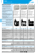
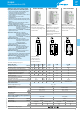
7P.21.8.075.1015 SPD Type 2, unipolar
protection suitable for DC
applications or low voltage AC
single phase systems
• Varistor protection +/– or L/N (GND); –/+ or GND (L/N)
• Replaceable module
7P.21.8.130.1015 SPD Type 2, unipolar
protection suitable for DC
application or low voltage AC
single phase systems
• Varistor protection +/– or L/N (GND); –/+ or GND (L/N)
• Replaceable module
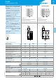
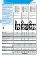
7P.21.8.275.x020 SPD Type 2, unipolar
protection suitable to realize
single phase or three phase
systems (230/400V)
• Varistor protection L/N(GND)-GND/(L/N)
• Replaceable module
7P.21.8.440.x020 SPD Type 2, unipolar
protection suitable for three
phase systems (400VAC)
• Varistor protection L/N(GND)-GND/(L/N)
• Replaceable module
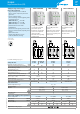
7P.22.8.275.x020 SPD Type 2 for single phase
system with Neutral
• Varistor protection L-N + spark gap protection N-PE
• Replaceable varistor and spark gap modules
7P.27.8.275.x020 SPD Type 2 for single phase
system with Neutral
• Varistor protection L, N-PE
• Replaceable varistor modules
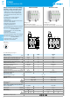
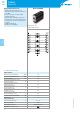
7P.21.8.xxx.x0xx 7P.22.8.275.x020 7P.27.8.275.x020
• SPD Type 2 (1 varistor)
• Replaceable varistor module
• Visual and optional remote
connector for signalling of the
varistor status
• SPD Type 2 (1 varistor + 1
spark-gap)
• Combination of replaceable
varistor and encapsulated
spark gap modules
• Visual and optional remote
connector for signalling of the
varistor status
• SPD Type 2 (2 varistors)
• Replaceable varistor modules
• Visual and optional remote
connector for signalling of the
varistor status
* 7P.20.8.075.0015
** 7P.20.8.130.0015
*** 7P.20.8.275.0020
**** 7P.20.8.440.0020
For outline drawing see page 14
SPD specification
075.1015 130.1015 275.1020 440.1020
L-N N-PE L, N-PE
Nominal voltage (U
N
) VAC/DC 60/60 110/125 230/— 400/— 230/— — 230/—
Maximum continous operating voltage (U
C
) VAC/DC 75/100 130/170 275/350 440/585 275/— 255/— 275/—
Nominal discharge current (8/20μs) (I
n
) kA 15 15 20 20 20 20 20
Maximum discharge current (8/20μs) (I
max
) kA 40 40 40 40 40 40 40
Voltage protection level at 5kA (U
P5
) kV 0.3 0.45 0.9 1.5 0.9 — 0.9
Voltage protection level at I
n
(U
p
) kV 0.4 0.6 1.2 1.9 1.2 1.5 1.2
Response time (t
a
) ns 25 25 100 25
Short-circuit proof at maximum
overcurrent protection kA
rms
50 25 50 — 50
Maximum overcurrent protection (fuse rating gL/gG) 160A 125A 160A — 160A
Replacement module code * ** *** **** 7P.20.8.275.0020 7P.20.1.000.0020 7P.20.8.275.0020
Other technical data
Ambient temperature range °C –40…+80
Protection degree IP20
Wire size solid cable stranded cable
mm
2
1x1…1x35 1x1…1x25
AWG 1x17…1x2 1x17…1x4
Wire strip length mm 12
Screw torque Nm 3
Remote status signalling contact specification
Contact configuration 1 CO (SPDT) 1 CO (SPDT)
Rated current AAC/DC 0.5/0.1 0.5/0.1
Rated voltage VAC/DC 250/30 250/30
Wire size (07P.01) solid cable stranded cable solid cable stranded cable
mm
2
1.5 1.5 1.5 1.5
AWG 16 16 16 16
Approvals (according to type)