
Datasheet

H
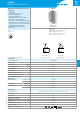
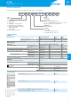
Multi-function and multi-voltage solid-state
output timer
• 17.5mm wide
• Six time scales from 0.1s to 24h
• High input/output isolation
• 35mm rail (EN60715) mount
• Multi-voltage output (24…240 VAC/DC),
independent from the input voltage
• “Blade + cross” - both flat blade and cross head
screw drivers can be used to adjust the range
and function selectors, the timing trimmer, and
to disengage the rail mounting clip
• Multi-voltage input with “PWM clever”
technology
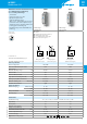
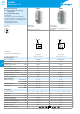
80.71
Screw terminal
80.71
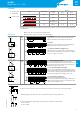
• Multi-voltage
• Multi-function
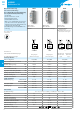
AI: On-delay
DI: Interval
SW: Symmetrical flasher (starting pulse on)
BE: Off-delay with control signal
CE: On- and off-delay with control signal
DE: Interval with control signal on
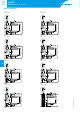
Wiring diagram
(without control signal)
Wiring diagram
(with control signal)
For outline drawing see page 6
Output circuit
Contact configuration 1 NO (SPST-NO)
Rated current A 1
Rated voltage VAC/DC 24…240
Switching voltage range VAC/DC 19…265
Rated load AC15 A 1
Rated load DC1 A 1
Minimum switching current mA 0.5
Max. “OFF-state” leakage current mA 0.05
Max. “ON-state” voltage drop V 2.8
Input circuit
Nominal voltage (U
N
) VAC (50/60Hz) 24…240
VDC 24…240
Rated power VA (50Hz)/W 1.3/1.3
Operating range VAC 19…265
VDC 19…265
Technical data
Specified time range (0.1…2)s, (1…20)s, (0.1…2)min, (1…20)min, (0.1…2)h, (1…24)h
Repeatability % ±1
Recovery time ms 100
Minimum control impulse ms 50
Setting accuracy-full range % ±5
Electrical life cycles 100·10
6
Ambient temperature range °C –20…+50
Protection category IP 20
Approvals (according to type)
3
II-2016, www.findernet.com
80
SERIES
80 SERIES
Modular Solid State timer (SST) 1A