
Deluxe Barbecue User Manual

6
Do not use a rubber hose within the enclosure for
the barbecue unit.
Apply only joint compounds that are resistant to all
gasses on male pipe fi ttings as required. Test each joint
with soap and water solution for leaks (never use a fl ame
to test for gas leaks). Make sure to tighten every joint
securely. Do not use pipe joint compound to connect
fl are fi ttings.
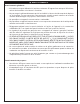
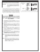
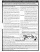
The gas supply pipe should enter from the rear wall of
the enclosure behind the barbecue unit, at least 2" (5.1
cm) from either side, and between 2" (5.1 cm) and 8"
(20.3 cm) above the fl oor, as illustrated by the shaded
area in
Fig. 6-3.
If it is not possible to stub the gas line in from the back of
the enclosure, the connection may be made through the
fl oor at the rear of the enclosure. Install the gas line stub
at least 2" (5.1 cm) away from the side and back walls,
but within 6" (15.2 cm) of the back wall, as illustrated by
the shaded area in Fig. 6-3.
Note: An external valve in the gas line is necessary
for safety when the barbecue is not in use. It
also provides for convenient maintenance and
repair. A removable key is recommended in
households with children.
GAS SUPPLY AND MANIFOLD PRESSURES:
Natural gas - Normal 7" (17.8 cm) water column (w.c),
minimum 5" (8.9 cm), maximum 10-
1
/
2
" (26.7 cm).
Propane gas - Normal 11" (27.9 cm) w.c., minimum 8"
(20.3 cm), maximum 13" (33 cm).
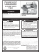
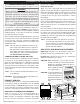
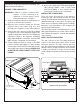
CAUTION: Wind blowing into or across the rear oven
lid vent can cause poor performance and/or
dangerous overheating. Orient the grill so
that the prevailing wind
blows toward the front
of the grill (Fig. 6-1).
CAUTION: To prevent dangerous
overheating, the rear
of the unit must have a
minimum clearance of
8” from any backsplash/
wall.
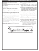
PLANNING FOR INSTALLATION
Fig. 6-2 - Ventilation diagram
Do not install this unit under overhead combustible
construction or unprotected fl ammable surfaces of
any kind (see EXHAUST REMOVAL section below for
exception). Do not install or use this appliance inside a
building, garage, or any other covered area, including
recreational vehicles or boats.
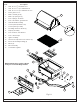
This is a slide-in type unit designed to fi t into open-front
enclosures. The control panel of the unit is removable
for gas hookup, servicing, and burner adjustment.
The control panel must therefore be removable after
installing the unit.
Note: This unit must be installed so that it can be
removed at a later date if service is required.
Any protrusion into the barbecue enclosure
may obstruct the frame and prevent the unit
from sliding into place (see GAS SUPPLY
PLUMBING REQUIREMENTS).
COMBUSTION AND COOLING AIR FLOW
Proper air fl ow must be maintained for the barbecue
to perform as it was designed (
Fig. 6-2). If airfl ow is
blocked, overheating and poor combustion will result.
Make sure not to block the 1" (2.54 cm) front air inlet
along the bottom of the barbecue control panel or the
air vent openings along the outside-left and right edges
of the frame.
Note: The 1" (2.54 cm) front air space allows access
to the drip tray.
CAUTION: Keep electrical supply cords away from
all heated surfaces.
EXHAUST REMOVAL
If installed under a patio roof, the grill area must be fully
covered by a chimney and exhaust hood. An exhaust
fan with a rating of 1,000 CFM (472 liters per second)
or more may be necessary to effi ciently remove smoke
and other cooking by-products from the covered area.
GAS SUPPLY PLUMBING REQUIREMENTS
Rigid
1
/
2
" (1.3 cm) or
3
/
4
" (.75 cm) black steel pipe,
or local code approved pipe for temperatures up to
800°F (427°C), is required to conduct the gas supply
into the enclosure opening for connection to the unit.
WHERE TO INSTALL YOUR BARBECUE
Fire Magic barbecues are designed for outdoor use only.
Fig. 6-3- Gas stub diagram
4"
2"
24
3/4"
20
3/4"
6"
12"
17
3/4"
Built-in models must be installed in masonry or
other type of fireproof enclosure. The unit is not
insulated, and therefore must be installed with
18" (45.7 cm) of side and back clearance from
unprotected combustible materials such as wood,
plastic, or stucco with wood framing, unless the
R. H. Peterson approved insulating liner for this
model is also installed.
WARNING
Fig. 6-1
CORRECT
Place grill so prevailing wind
blows toward front of grill
REV 4 - 1406201510
L-C2-147