
Owners Manual


11
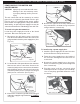
INSTALL THE FLAME COLLIMATOR
1. Place the fl ame collimator over the burner with
the tabs and cutouts resting on the inner liner
shelf, as shown in Fig. 11-1. Flex the front of the
collimator towards the burner until the cut outs fi t
down around the collimator support. This will lock
your collimator into place. The fl ame collimator
acts as a barrier for windy conditions and creates
higher BTU concentration in the cooking grid.
2. When using a wok for stir fry cooking, remove
the grid and the wok will be supported by the
collimator.
REMOVE THE CONTROL PANEL TO CHECK
RATING PLATE
The control panel may be removed to access the
rating plate and check for the gas type of your power
burner.
1. Turn off the gas shutoff valve.
Pull off the control
knobs. Slowly lift away the lighted bezels to clear
the valve stems, and carefully disconnect the wires
found on the back of the bezels (use your fi ngernail).
See Fig. 11-1. Unscrew and remove the control
panel screws and washers.
INSTALLING YOUR FIRE MAGIC POWER BURNER (Cont.)
2. Carefully lift the control panel away from the
frame.
3. Check the rating plate for gas type.
Important: If converting the gas type, see the
CHECKING AND CONVERTING
THE REGULATOR section before
replacing the control panel.
4. Replace the control panel. Reconnect the
bezels and secure in place. Replace the control
knobs.
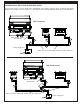
ADJUST THE AIR SHUTTERS
Power burner air shutter(s) are located on the necks
of the power burner as shown in Fig. 11-2.
CAUTION: DO NOT handle a hot burner without
adequate hand protection.
To adjust the air shutters:
1. See step 2 under
the CHECK FUEL
ORIFICES FOR
PROPER SIZE
section.
2. Lift the back of the
burner upward so
that the burner stud
in the bottom back
clears the locator
hole in the burner rest.
3. Move the burner back away from the front of the
power burner while continuing to lift the back
upward so that it clears the rear fi rewall.
4. Turn the shutter to the desired opening size
and replace the burner to test the effect on the
fl ame (see LIGHTING INSTRUCTIONS).
Burner flames should burn evenly (mostly
blue). A proper fl ame pattern will ensure safe
operation and optimal performance.
Fig. 11-2
Air shutters
Fig. 11-1
Bezel
removed
Carefully
disconnect
Fig. 11-1 Placing the fl ame collimator
Cut
outs
Flame
Collimator
Collimator support
Collimator support
T abs