
Owners Manual

8
Perform the following checks before installing your
power burner:
CHECK FUEL ORIFICES FOR PROPER SIZE
1. Your Fire Magic power burner is equipped with
fuel orifi ces for natural gas, unless otherwise
indicated. To change the gas type, you must install
different orifi ces to avoid hazardous overheating.
(Refer to Table 1 for the proper orifi ce size)
IMPORTANT: When converting orifi ces for different
gas type, the regulator must also
be converted for the new gas type.
Reference the REMOVE THE
CONTROL PANEL and CONVERTING
THE REGULATOR sections.
2. Remove the cooking grid. Grip the flame
collimator and remove it by compressing the ring
slightly front to back and lifting the compressed
end upward. Reference the fi gure in the INSTALL
THE FLAME COLLIMATOR section.
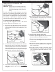
3. Check the orifi ce size by lifting the burner up and
out of the locator hole and pulling it away from
the orifi ces. The orifi ce size is stamped on the
orifi ce face. Be sure not to lose the air shutter or
air shutter spring which may become detached
when the burner is removed.
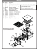
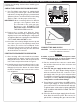
POSITION THE BURNER FOR OPERATION
1. After checking orifi ce size install the air shutter
spring and the air shutter over the orifi ce holder
fi tting, between the burner and the heat shield,
in the order and position shown in Fig. 8-1.
2.
Carefully place the burner stud back in the locator
hole so that the brass orifi ce and orifi ce holder
fi ttings project into the burner air venturi. When
the burner stud fi ts in the locator hole the orifi ce
is in alignment.
INSTALLING YOUR FIRE MAGIC POWER BURNER
Fig. 8-1
Burner air venturi
Orifi ce
CONNECT THE GAS SUPPLY
CAUTION: Use only C.S.A. listed stainless-steel fl ex
connectors within the enclosure.
WARNING
A rubber or plastic connector will rupture or leak,
resulting in an explosion or serious injury if used
inside the appliance enclosure.
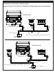
1. Run the attached fl ex connector routed under
the left side of the unit out of the enclosure and
to the gas stub.
2. Turn OFF the gas supply at the source. Then
connect the
1
/
2
" pipe adapter fi tting supplied
with the stainless-steel fl ex connector to the
gas-supply stub. Use pipe joint compound that
is resistant to all gasses on the male pipe fi tting
and tighten securely. DO NOT use pipe joint
compound to connect fl are fi ttings.
3. Turn all burner control knobs to the OFF position.
Turn the gas supply on. Then carefully check all
gas connections for leaks with a brush and half-
soap/half-water solution before lighting. NEVER
USE A MATCH OR OPEN FLAME TO TEST
FOR LEAKS.
4.
Close the dedicated gas-supply shut-off valve,
then slide the unit into place. Be sure not to
pinch, kink, or damage the gas connector line.
Fig. 8-2 Sliding into place
Fig. 8-4
TO GAS SUPPLY