
User Manual for Powe Burner Diamond Series

10
L-C2-333
REV 3 - 1601181405
The control panel MUST remain removable for servicing
(see PARTS LIST).
EXHAUST REMOVAL
If the unit is installed under an overhead structure, it
must be constructed of non-combustible material. An
exhaust hood is recommended. See below.
When using an exhaust hood:
The cooking grid area must be covered by an exhaust
hood (with a vent) larger than the cooking surface. Refer
to manufacturer specifi cations. An exhaust fan with a
rating of 1,000 CFM (cubic feet per minute) (472 liters
per second) or more may be necessary to effectively
remove smoke and other cooking by-products from the
area under the hood. RHP Vent Hoods are available,
contact your local dealer.
THIS UNIT MUST NOT BE LOCATED IN A FULLY
ENCLOSED AREA OF ANY KIND.
ENSURE PROPER COMBUSTION AIR AND
COOLING AIRFLOW
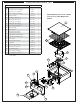
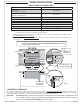
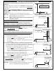
Proper airfl ow (Fig. 10-1) MUST be maintained for the
power burner to perform as it was designed. If airfl ow
is blocked, overheating and poor combustion will result.
Do not block the 1" front air inlet along the bottom of
the control panel or more than 75% of the cooking grid
surface with pans or griddles.
GAS-SUPPLY PLUMBING REQUIREMENTS
For natural gas or a household propane system, rigid
1
/
2
" or
3
/
4
" black steel pipe or local code-approved pipe
is required to conduct the gas supply to the unit. Contact
your local gas supplier. Connect this pipe to a required
C.S.A.-approved stainless-steel fl ex connector. DO NOT
use a rubber hose within the unit enclosure. Apply
only joint compounds that are resistant to all gasses to
all male pipe fi ttings except fl are fi ttings. Make sure to
tighten every joint securely.
Note: If
1
/
2
" pipe is used with natural gas, it should
be no longer than 20'.
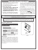
Important: A shut-off valve (not included) in
the gas line is required. It provides
for safety when the unit is not in use
and for convenient maintenance and
repair. It must be installed within 6 feet
of the unit. Use a pipe joint compound
resistant to all gasses on all male
fi ttings except fl are fi ttings.
GAS SUPPLY AND MANIFOLD PRESSURES:
For natural gas - normal 7" water column (w.c.),
minimum 3
1
/
2
", maximum 10
1
/
2
". For propane gas -
normal 11" w.c., minimum 8", maximum 13".
Fig. 10-1 Ventilation Diagram
INSTALLATION REQUIREMENTS (cont.)